introduction
With the increasing awareness of people's safety, the demand for monitoring equipment is gradually increasing. More and more occasions require the use of embedded monitoring equipment for data recording and security. With embedded monitoring equipment, it can replace the naked eye and achieve comprehensive, safe and stable monitoring. Portable embedded monitoring equipment belongs to a special category of embedded monitoring equipment. The equipment is small in size, light in weight, portable, fast, safe and stable, and long-lasting. This equipment is often used to record law enforcement processes, sudden traffic incidents, etc., in order to obtain timely and reliable on-site evidence, which avoids the problem that traditional monitoring equipment is difficult to carry around, has the problem of monitoring dead angles, and avoids the lack of sufficient on-site evidence. The case of misjudgment. Based on the characteristics of portable embedded devices, equipped with efficient communication technology can enhance the practical application value of the device. Therefore, the portable monitoring system solution based on TMS320DM365 has certain practical significance.
1 hardware design
1.1 Overview of Hardware Devices
Embedded devices have a basic hardware system and generally include the following three components:
1 core components: microprocessor, clock circuit.
2 main components: storage devices, test channel devices, human interface components, communication interface components.
3 basic components: power supply circuit, circuit monitoring circuit, reset circuit, electromagnetic compatibility and interference suppression EMC / EMI circuit.
When selecting the hardware for the portable embedded monitoring device, it is necessary to consider whether the computing power of the processing core satisfies the requirements for the collection and processing of high-definition audio and video; whether the storage device has enough space to accommodate the high-definition audio and video data with a large amount of data; Whether to achieve high-speed, stable, and secure transmission of digital signals. While satisfying the above functions, because of the particularity of the portable embedded monitoring device, it is necessary to select hardware devices with lower power consumption, and after the basic requirements are met, other devices should be tailored, such as display/printing devices, keyboard input devices, etc. .
1.2 hardware equipment design
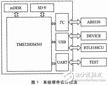
Texas Instruments' TMS320DM365 (hereafter referred to as DM365) has a fast computing speed, can be accelerated by coprocessor during encoding, and supports large-capacity storage media, which is enough to meet the needs of monitoring equipment. At the same time, its peripheral circuit design is simple, which can greatly reduce the size of the device; the processing core is ARM core, the power consumption is relatively low; the memory uses low power consumption and small volume mDDR as the memory module; the Micro SD card is selected as the storage device. Use it instead of NAND Flash to store systems and applications; communication uses USB interface and WiFi module; video capture uses ATPINA's AR0330 module. The hardware design block diagram is shown in Figure 1.
2 software design
2.1 Software Architecture Design
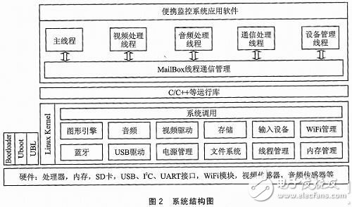
The Linux system is a hardware-based Unix-like operating system that includes hardware drivers, power management, file systems, and thread management modules to provide basic system calls. Linux provides a POSIX-compliant C/C++ runtime library. Based on DM365 hardware devices, UBL and Uboot are required to boot the Linux system. The application software is based on this system design. The system structure diagram is shown in Figure 2.
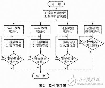
The portable monitoring system application software is built on a basic Linux system, including the main thread and four main sub-threads for video processing, audio processing, communication management, and device management. The flow chart of the software operation is shown in Figure 3.
2.2 Audio/Video Capture, Coding and Storage Design
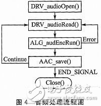
The audio uses the audio acquisition method of the DM365 processor. The encoding adopts AAC compression mode and uses a new algorithm for encoding, which has higher cost performance. With the AAC format, the sound quality can be made smaller without a significant reduction in sound quality. In the software implementation process, use TI's API function combined with Linux system design; use DRV_audioOpen() and DRV_audioRead() function to realize audio hardware initialization and read data; use ALG_audEncRun() function to perform audio AAC encoding, and write Program to achieve encoded data storage. In the above process, parameter configuration of the API function is required. The processing flow is shown in Figure 4.
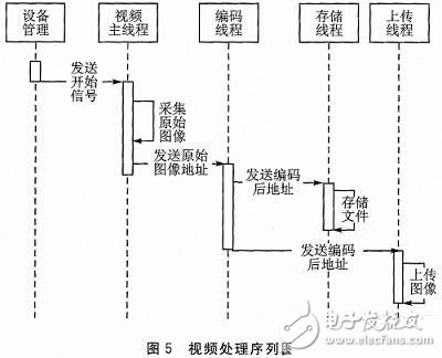
The video is captured by the image sensor AR0330 of the I2C interface to read the video stream information, and the white balance is performed by the on-chip ISP. Each time one frame of image is read, the image is encoded and saved. The video encoding is in JPEG mode and is packaged as a .jpg image file for storage. Use the DRV_captureStart() function to initialize the camera; call the ALG_aewbRun() function for auto exposure and auto white balance; use the DRV_ipipeGetRszBuf() function to read in 1 frame; pass the data to the SnapshotFrameDataEx() function for JPEG encoding. The program will start the storage thread to save the encoded file in the storage device, then start the upload thread and upload the image to the client. The video processing sequence diagram is shown in Figure 5.
2.3 Communication scheme design
This scheme uses the wireless transmission method based on WiFi technology as the basic medium, and realizes the Socket transmission strategy based on TCP/IP protocol by software, which ensures the stability and security of data transmission while ensuring the transmission speed. The wireless network access point (AP) is set up so that other devices (such as computers, mobile phones, tablets, etc.) can be connected to the portable monitoring device through WPA2 encryption to ensure data exchange while ensuring sufficient security.
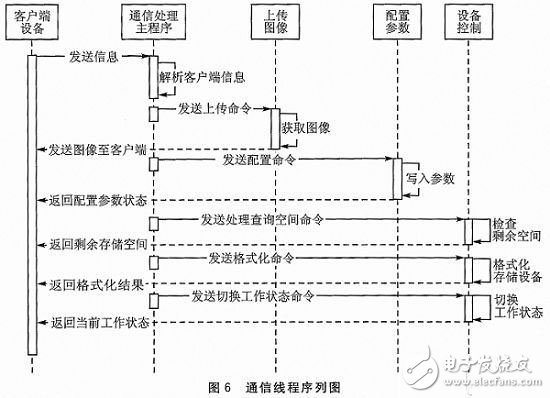
After the AP is set up, the Socket server is implemented by software to ensure the complete implementation of the transmission function. After the connection is established, a separate thread is used to complete the data communication between the monitoring device and the client device.
In this thread, the function of real-time monitoring data uploading and receiving control commands sent by the client is implemented. The communication thread sequence diagram is shown in Figure 6.
2.4 System operation plan design
During the operation of the monitoring system, the microprocessor, storage device and other necessary circuits must maintain the power supply status at any time, and other devices can manage the power on and off according to the usage. Therefore, in order to better control power consumption, it is necessary to perform power management on the video capture device and the communication device in software.
For the video capture device, the operation mode of photographing 3 times per second during the operation of the portable monitoring device can ensure the continuity of the monitoring and control the power consumption of the video capturing device and the image encoder. When a photo is required, the video capture device and the image encoding accelerator are activated to perform image acquisition and encoding. When the 3 shots are over, the video capture device is paused and the power of the image encoding accelerator is turned off. The image acquisition speed of this design is 30 fps, so the above process can make the system 90% of the time in a low power state, which greatly reduces the average power consumption of the system.
For communication devices, a WiFi module is used for data communication. When the system does not need to send data to the outside, the driver of the WiFi device is uninstalled by software, and the power consumption of the WiFi device is low. When data communication is required, the driver of the WiFi device is loaded to implement data transmission. After the transfer is complete, the WiFi function can be turned off and the driver can be uninstalled to restore the WiFi device to a low power state.
2.5 Android mobile phone program design
This paper uses the mobile phone software based on Android system as the client software, which communicates with the portable monitoring system to realize real-time display and storage of the monitoring screen and control it. Therefore, it is necessary to design Socket communication, picture display and storage, local file writing and reading, interface drawing, thread operation, and the like. The specific functions realized are as follows: (1) connecting the server on the portable monitoring device through the IP address and the port number; 2 receiving and displaying the monitoring screen in real time, and optionally storing the received picture locally; 3 configuring the AP parameter and system time of the server, And save the configuration information; 4 control the monitoring system to store the monitoring screen, query the available space, format the storage area of ​​the monitoring system.
The client software communicates with the server on the portable monitoring device through the Socket and implements the above functions, so a simple communication protocol needs to be established. For different operations, different command control words are defined, and the command control word occupies 4 bytes. After receiving the command control word, the server determines its legality and performs it according to the preset corresponding function. The client proceeds to the next step by receiving and judging the command control word returned by the server.
Conclusion
The hardware device of the portable monitoring system was designed and implemented, and the software solution was tested. The experimental results show that the DM365-based portable monitoring system solution proposed in this paper can effectively reduce the hardware volume and reduce power consumption. Increased flexibility and usability of the device through interaction with other portable devices.
Residential Energy Storage System
Enershare's commitment to future-ready energy solutions for smart home innovations, Enershare`s Energy Storage Systems create a flexible energy maintenance system for homeowners who want to take more control of their home energy use, it is intended to be used for home battery energy storage and stores electricity for solar self-consumption, load shifting, backup power, and off-the-grid use. you can use it anytime you want-at night or during an outage.
Home Battery,Home Battery Backup,Home Energy Storage System,Battery Backup Power Supply For Home,High Capacity Electrical Backup,Power Bank For Home
Shenzhen Enershare Technology Co.,Ltd , https://www.enersharepower.com