1 Introduction
Compared with the traditional electret condenser microphone, the capacitive MEMS microphone has the following advantages: 1) stable performance, low temperature coefficient, low influence by humidity and mechanical vibration; 2) low cost; 3) compact size, capacitive The back plate and diaphragm of the MEMS microphone are only about 1/10 of the smallest electret condenser microphone; 4) the power consumption is lower. The advantages of the above aspects make capacitive MEMS microphones more and more widely used.
However, capacitive MEMS microphones also present challenges for designers: 1) the small signal amplitude generated by the microphone under the action of sound pressure is very small, requiring the noise of the readout circuit to be extremely low; 2) the static capacitance of the capacitive MEMS microphone is pF On the order of magnitude, the readout circuit requires an input resistor of the order of GΩ to achieve a high-pass filter with a pole frequency below 20 Hz. Therefore, the implementation of a high-resistance resistor is another challenge for the readout circuit; 3) The capacitive MEMS microphone is usually applied. For battery-powered products, low-power design is also a constraint that must be considered when reading out circuit designs.
Based on the above considerations, based on the analysis of the working principle of capacitive MEMS microphone, a low-power, low-noise, high-resolution capacitive MEMS microphone readout circuit is proposed.
2 capacitive MEMS microphone
2.1 Working principle
The main structure of a capacitive MEMS microphone consists of a thin, flexible acoustic diaphragm and a rigid back plate. The diaphragm, the back plate and the air gap between them form a parallel plate capacitor, so:
V=Q/C, C=εS/x (1)
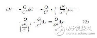
Where C is the capacitance, S is the area of ​​the plate, Q is the amount of charge stored when the voltage between the plates is V, ε is the dielectric constant of the medium (air) between the plates, and x is between the plates distance. When the sound pressure change of the dP size acts on the diaphragm, it will cause a voltage change between the two plates:

Since dxâˆdP, the output voltage dVâˆdP. This is the principle of acoustic-electric conversion of a capacitive MEMS microphone.
The condition for this principle is established: in the process of acoustic-electrical conversion, it is necessary to keep the charge Q stored in the microphone capacitor constant, so it is necessary to add a stable DC voltage to charge the capacitor to maintain a constant state of charge. This function is implemented by a charge pump.
2.2 Microphone readout circuit structure
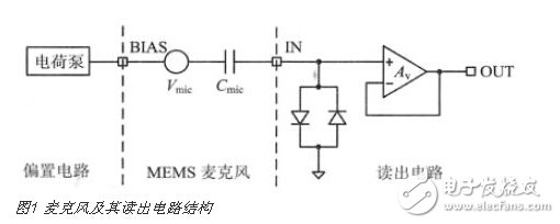
The system consisting of a capacitive MEMS microphone and its readout circuit is shown in Figure 1.

The charge pump provides a stable DC voltage to the microphone to keep the amount of charge stored in the microphone capacitor constant. On this basis, when the sound pressure acts on the diaphragm, it will cause a change in the voltage between the two poles of the microphone. The voltage small signal Vmic in this audio range is high-pass filtered by the microphone capacitor Cmic and the high-resistance input resistance of the readout circuit. Read out.
It is important to note that the back-to-back diodes serve three purposes: 1) providing a high-impedance input resistor, a high-pass filter with a low-pole frequency with the microphone capacitor, and thus a small signal reading of the microphone; 2) providing a unity-gain buffer DC bias voltage; 3) Static protection, providing a low-resistance DC path when the readout circuit is subjected to electrostatic attack. The function of the unity gain buffer is to shield the microphone and the subsequent signal processing circuit to avoid mutual influence between the two, and to improve the driving capability of the readout circuit.
Dropout Fuse Cutout and load drop fuse cutout are outdoor used high-voltage protective devices. They are connected with the main lines of the distribution transformer or the distribution wires to protect the transformer or wires from short circuit and overload, and on/off loading current. Dropout fuse cutout consists of insulating bracket and fuse tube. The static contacts are fixed on the two ends of bracket, while the moving contacts are fixed on the two ends of fuse tube. Fuse tube is composed of inner extinction tube and the outer epoxy glass tube. The load drop fuse cutout is added with elastic supporting contacts and arcing shield for switching on-off loading current. In normal operation, the fuse tube will form an enclosure via its tightened fuse link. The fuse will be melt off quickly and form an arc if there is any fault, the extinction tube is heated by the arc, exploding much gas to give high pressure into the tube and blow along with the tube, so the arc is quickly elongated and extinguished. When the fuse is cut off, moving contacts at the bottom turn down without tension; the locking frame will release the fuse, so the fuse drops to form obvious break. When it needs to put load on, start the contact with insulating cod, then the static and moving contacts are still keeping in touch, keep pulling the contacts till the supporting contacts apart. Then there is the arc among the supporting contacts, which is prolonged in the narrow space of arcing shield.At the same time, the arc extinguishing cover generates gas, and the arc is extinguished when the current exceeds zero.
Porcelain Fuse Cutout,Drop Fuse Cutout,Fuse Link Cut Out,Cutout Fuse Holder
Jilin Nengxing Electrical Equipment Co. Ltd. , https://www.nengxingelectric.com