equipment
1. Yonghong plc: FBS-24MCT1
2.GSK servo 1 set: Di20-M10B (driver) / 80SJT-M032E (motor)
3.DC24V switching power supply 1
4. Signal Lines Several View Driver Pin Definitions and Select Control Mode Position Control Mode: View the servo pin definition, where the motor rotation is achieved with a minimum of signal lines.
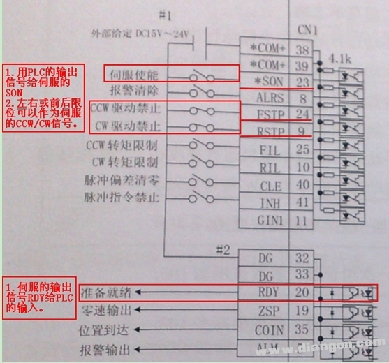
SON: When ON, the servo enable is enabled. Of course, the servo enable function can be modified by parameters, which can be set by parameter PA54.
PA54=0: The motor can be enabled only when the external input signal SON is ON;
PA54=1: The drive unit internally forces the motor to be enabled without the external input signal SON.
CCW/CW: Drive disable signal, generally used in conjunction with the travel switch to avoid overtravel, this signal can be set by parameter PA20.
PA20=0: Use the drive inhibit function;
PA20=1: Do not use the drive hex function.
RDY: The drive unit is ready for the signal, which has an output when the motor is energized.
Position command input signal 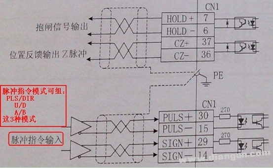
Here, the position input signal can be differential drive or single-ended drive connection. Since the selected FBS-24MCT is an open collector output form, a single-ended drive connection is used.
When the servo drive single-ended drive mode limits the external power supply to a maximum voltage of 25V, a current limiting resistor R needs to be connected in series.
According to: Vcc=24V, R=1.3KΩ~2KΩ; Vcc=12V, R=510KΩ~820KΩ; Vcc=5V, R=0;
The frequency limit is:
PLS/DIR: highest pulse frequency 500KHZ
U/D: highest pulse frequency 500KHZ
A/B: highest pulse frequency 300KHZ
Control line production
The GSK comes with a 44-pin socket that connects the required control signals according to the pin map. Here, it is possible to connect the signal lines that are likely to be used, but these signals are not necessary in the servo control. In the figure below, the blue line indicates the servo output signal to the PLC input, and the red indicates the PLC output. For the input of the servo, the positive and negative of the switching power supply are indicated by red and blue respectively.
1) Select the desired control signal
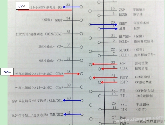

2) Wiring diagram of servo and PLC Here, only the SRDY is taken from the input signal from the servo to the PLC. The signals given by the PLC to the servo are SON, FSTP (CCW), RSTP (CW), and PULS/SIGN. 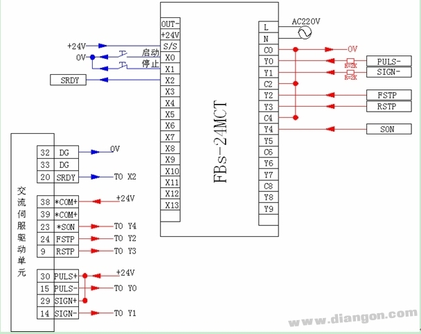
Servo debugging · Take out the driver, motor, motor to drive encoder cable and motor to drive power cable, the factory has been configured, just follow the instructions.
• Connect the PLC to the drive control signal line.
1. Manual debugging of servo
1) Servo parameter setting
After the GSK servo is powered on, you can first use the manual function that comes with the drive itself. In this function mode, the servo rotation is controlled by the drive button, enter the PA parameter menu, and set the parameters:
PA4=3: Manual mode, operate under the SR-menu, use the ↑ and ↓ keys to perform the acceleration and deceleration operations.
PA20=1: The drive disable function is invalid. At this time, only the drive itself is used for debugging, so the CCW\CW function is first masked.
PA54=1: The internal forced motor of the drive unit is enabled without the external input signal SON.
After the parameter setting is completed, power off after saving.
2) Manual operation steps
1. The drive is powered on and the display R - 0 is the motor running speed monitoring window.
2. Check that the PA1 parameter is consistent with the motor code used.
3. After the above 2 steps are correct, after entering the “SR- /SR-RED†menu, press the ↑ and ↓ keys to start running the motor.
2. PLC control running servo runs normally under manual debugging, and now enters the upper control of PLC. The IO introduced by the servo from the servo in this control is as follows:
Input:
SRDY - X2
Output:
PULS-: Y0
SIGN-: Y1
CCW: Y2
CW: Y3
SON: Y4
For the convenience of control, the CCW\CW signal is first enabled to be shielded.
1) Servo parameter setting
PA4=0: Position mode.
PA12: Electronic gear multiplication factor (electronic gear numerator), set to 2.
PA13: Electronic gear division factor (electronic gear denominator), set to 1.
PA14=0: Pulse mode input mode: pulse + direction.
PA15=0: The position command direction maintains the original command direction.
PA20=1: The drive disable function is invalid (ie, the CCW/CW enable signal is masked).
PA54=0: External SON is enabled.
After the parameters are modified, power off after storage and power on again.
2) Relevant calculations Here we first make a multi-speed running program of the servo motor, the motion process
1. Turn 10 times at speed 1000RPM
2. Then turn 20 rpm at speed 1200RPM
3. Then turn 30 times at speed 1400RPM
4. Then turn 40 laps at speed 1600RPM
5. Then turn to lap at speed 1800RPM
6. Then run 60 laps at rated speed 2000RPM
7. After a certain period of pause, repeat from step 1.
It is known from the manual that the encoder feeds 10,000 rpm for each revolution, and the electronic gear is set to 2, so every time the PLC issues 5000PS, the servo rotates one revolution, that is, the first stroke 10 pulses corresponds to the number of pulses = 10 circles × 5000PS /circle=50000PS
The stroke pulse count of other segments is the same as this.
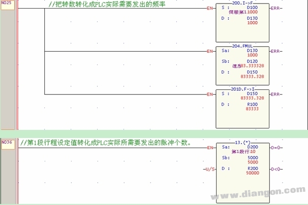
Convert the speed required by the servo into the number of pulses of the PLC. Take 1000 RPM as an example. Suppose the number of pulses that the PLC needs to send is X, and the electronic gear setting is 2, then you get: X=83333.3HZ
With this formula, the number of PLC pulses corresponding to other speeds can be obtained.
3) Setting of PLC parameters
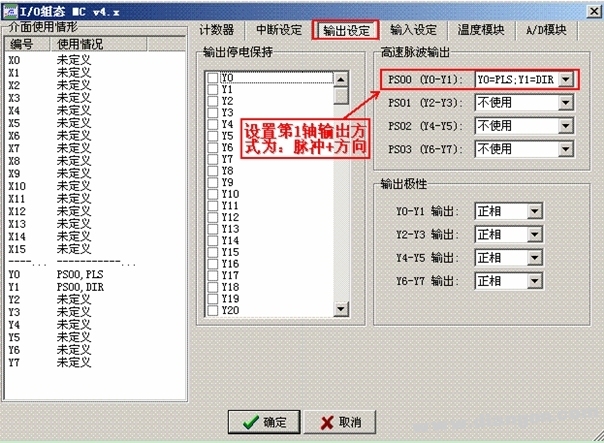
The pulse output point of FBS-24MCT has 4 axes (8 points), which is Y0~Y7. The default Y0~Y3 is high speed 200K, and Y4~Y7 is medium speed 20K. To make the PLC's high-speed point output pulse, you need to configure the output of these points first. Click “Project\IO Configuration†in the menu bar of Yonghong programming software to enter the configuration page.
4) Programming of the program
After the setup is complete, you can enter the program. 

5) Edit the NC positioning table. Click the FUN140 command with the left mouse button, and then press the Z key on the keyboard to enter the NC positioning table in the English input state. The final result is as follows: 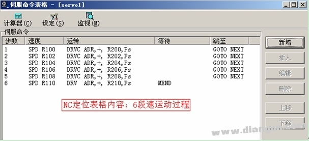
6) Subprogram content
The INIT subroutine mainly does some initialization, as follows 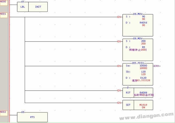
The SPEED subroutine mainly converts the input speed and formation into the number of pulses required to be generated by the PLC. Here, the conversion of the first speed and stroke is taken as an example. Since the rated speed of the servo is 2000 RPM, the speed is set. When you want to prevent the input number of revolutions from exceeding this value. 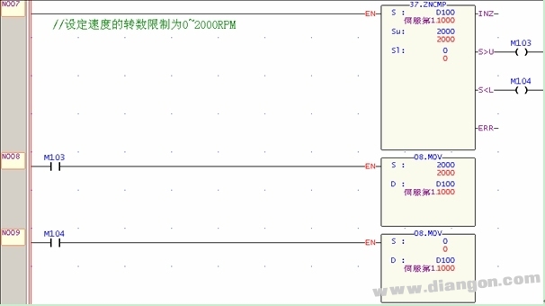
7) After the power-on running debugging program is completed, let the PLC be in the RUN state, and perform numerical monitoring on the input page, as follows 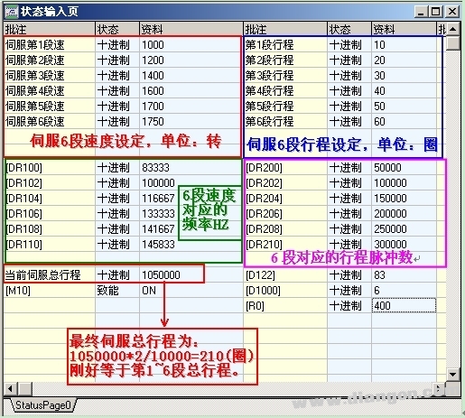
Summary Since the input signal of the PLC in this example only grabs SRDY from the servo, the other point wiring is the same as the SRDY connection. The signal that the PLC outputs to the servo is only PLS\DIR and SON, and the connection of other signals is similar. The GSK servo requires only a few control lines to operate the servo. The positioning commands of the Yonghong PLC are all filled in the NC form.
10inch Tablet,Kid Tablet,Android Tablet,WiFi Tablet
C&Q Technology (Guangzhou) Co.,Ltd. , https://www.gzcqteq.com