UC3842A UC3843A Chinese information
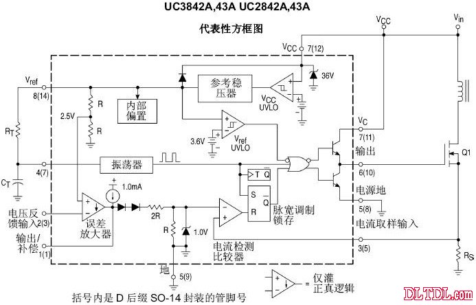
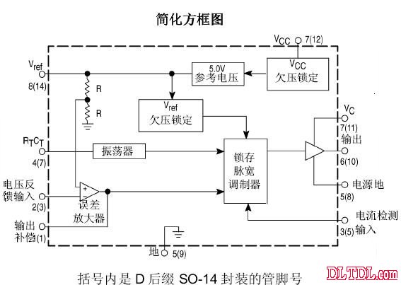
The UC3842A UC3843A is a high performance fixed frequency current mode controller designed for off-line and DC to DC converter applications, providing designers with a cost-effective solution with minimal external components. These integrated circuits feature a trimmable oscillator, accurate duty cycle control, temperature compensated reference, and a high gain error amplifier. The current sampling comparator and the high current totem pole output are ideal for driving power MOSFETs.
Other protection features include input and reference undervoltage lockout, each with hysteresis, cycle-by-cycle current limit, programmable output dead time, and single pulse measurement latch. These devices are available in 8-pin dual in-line plastic packages and 14-pin plastic surface mount packages (SO-14). The totem pole output stage of the SO-14 package has separate power and ground pins.
The UC3842A has 16V (pass) and 10 volt (off) low voltage lockout thresholds, making it ideal for off-line converters. The UC3843A is designed for low voltage applications with low voltage lockout thresholds of 8.5 volts (pass) and 7.6 volts (off).
Features:
Fine-tuned oscillator discharge current for precise duty cycle control.
Current mode works to 500KHZ
Automatic feedforward compensation Latch pulse width modulation, cycle-by-cycle current-limit internally trimmed reference voltage with undervoltage lockout High current totem pole output Undervoltage lockout with hysteresis Low start-up and operating current Direct interface with ON Semiconductor's SENSEFET products


figure 1

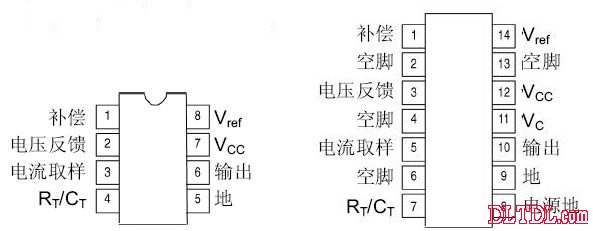
Figure 2 pin diagram
Pin Function Pin Function Description 8 Pin 14 Pin 11 Compensates This pin is the error amplifier output and can be used for loop compensation. 23 Voltage Feedback This pin is the inverting input of the error amplifier and is typically connected to the switching power supply output through a resistor divider. 35 Current Sampling A voltage proportional to the inductor current is connected to this input, and the pulse width modulator uses this information to abort the conduction of the output switch. The 47RT/CT adjusts the oscillator frequency and maximum output duty cycle by connecting resistor RT to Vref and capacitor CT to ground. The working frequency can reach 500kHz. 5 - Ground This pin is the common ground for the control circuit and power supply (only for the 8-pin package). The 610 output directly drives the gate of the power MOSFET. The peak current of up to 1.OA is pulled and filled through this pin. The 712VCC pin is the positive supply for the control IC. The 814Vref pin is the reference output, which supplies the charging current to the capacitor CT through the resistor RT. 8 Power Ground This pin is a separate power return to the power supply return (14-pin package only) to reduce the effects of switching transient noise in the control circuit. The 11VC output high state (VoH) is set by the voltage applied to this pin (14-pin package only). The effect of switching transient noise on the control circuit can be reduced by a separate power connection. The ground pin is the return end of the control circuit (only the 4-pin package is so) and is connected back to the power ground. 2, 4, 6, 13 empty feet are not connected (only 14-pin package is so). These pins have no internal connections.
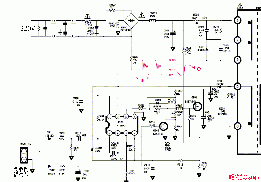
The following figure shows the UC3842 application circuit diagram of a display.

image 3
UC3842 good and bad judgment and identification method Among the domestic electronic equipment, the most commonly used integrated circuit model of the power supply PWM control circuit is UC3842 (or KA3842). It is because it is often encountered, and there are some things for it. Here is a brief introduction to the judgment method of UC3842:
After replacing the damaged components, do not install the switch (MOSFET), power up to measure the voltage of 7 pin of UC3842. If the voltage fluctuates between 10-17V, the other legs also have fluctuating voltages respectively, indicating that the circuit has Starting, UC3842 is basically normal; if the voltage of pin 7 is low, the other pins have no voltage or do not fluctuate, then UC3842 is damaged.
Add a DC voltage of about +17V between pins 7 and 5 of UC3842. If the pin 8 has a voltage of +5V and the voltages of 1, 2, 4, and 6 also have different voltages, the UC3842 is basically normal, the working current is small, and it is not easy to damage itself. . The most common cause of damage is that after the short circuit of the power switch (MOSFET), the high voltage is applied from the G pole to its 6 pin, causing it to burn. In some models, the G-grounded protection diode is omitted. When the power switch (MOSFET) is damaged, the current limiting resistors of the UC3842 and G poles must be damaged. Simply replace it at this time.
It should be noted that the source (S pole) of the power switch is usually connected to a small resistance, high-power resistor as an overcurrent protection detection resistor. The resistance of this resistor is generally between 0.2 and 0.6. Above this value, there is a phenomenon that the load cannot be loaded (that is, the voltage of the secondary pole is low).
Since the working voltage and output power of UC3842 (KA3842) are far from UC3843 (KA3843), the 3842 series and 3843 series also have a big difference in starting voltage and closing voltage. The former has a starting voltage of 16V, and the voltage is turned off. It is 10V; the latter has a starting voltage of 8.5V and a shutdown voltage of 7.6V. These two series of ICs cannot be replaced directly. If it is necessary to replace the former with the latter, the circuit must be modified. Therefore, this must be paid attention to in the maintenance work. Maintenance failure
China Base Stations Antennas,High gain Base Stations Antennas.Factory Price Base Stations Antennas
Panel Antenna,Yagi Antenna.Directional Antenna,Parabolic Dish Antenna,parabolic grid antenna
Yetnorson Antenna Co., Ltd. , https://www.xhlantenna.com