0 Preface
The advancement of LED technology has provided new opportunities for the design of LED spotlights. High-power white LEDs have gradually replaced traditional halogen lamps and become new light sources for spotlights. However, the photoelectric conversion efficiency of LED is low, and nearly 80% of the energy is converted into heat energy, which causes the LED spotlight to be severely heated. The improper design of the LED spotlight heat will cause the junction temperature of the LED chip to be too high, the life of the device is shortened, and the light effect is reduced.
The LED spotlight has a complicated structure and small volume. It is difficult to measure the temperature field distribution of the LED chip by experimental methods. The heat sink is designed mainly by qualitatively comparing the heat dissipation capability of the heat sink. Yu Binhai et al. proposed a quantitative calculation of LED devices using a “thermal resistance network modelâ€. The method can calculate the heat dissipation capability of the whole lamp system, but can not quantitatively calculate the relationship between the convection area of ​​the heat sink and the power consumption of the LED, and it is difficult to simplify the processing for the complex model, and the calculation accuracy is low. In addition, there are no published documents on the quantitative relationship between the design of the spotlight heat sink, such as the quantitative matching between the internal channel conduction capability and the external channel convection capability, and the quantitative matching between power and convection area. .
In this paper, an MR16LED spotlight is used as a model, and ANSYS finite element software is used to analyze the influence of each component of LED spotlight on the heat dissipation performance of the whole system. The quantitative relationship between power and convection area is emphasized. At present, the heat treatment technology of LED lamps at home and abroad, the temperature of the fins of the radiator is basically set at about 60 °C. The thermal simulation analysis shows that to maintain the surface temperature of the MRl6 spotlight radiator at around 60 °C, the existing radiator can only meet the 2.5W LED spotlight, and the quantitative analysis provides practical guidance for the radiator production.
1 Establishment of finite element theory model and solid model
According to the heat transfer theory, the temperature field variation of the MRl6 LED spotlight with internal heat source is satisfied.

Where: such as Kxx, Kyy, Kzz are the thermal conductivity of the model in the x, y, z direction; q" is the heat generation rate of the internal heat source; Ï is the density; c is the specific heat capacity; T is the temperature. The heat transfer differential equation Converted to an equivalent integral form

Where: Ts, Ts are the surface temperature and air temperature of the radiator respectively; h is the convection coefficient of air and radiator; V is the unit volume;  ; S2 is the heat flow boundary; S3 is the convection area.
The junction temperature of the LED is generally not higher than 125 ° C, and the heat is mainly radiated in the form of conduction and convection, ignoring radiation dissipation. The surface of the radiator is thermally convected with the outside air according to the Newtonian cooling equation

Where q is the heat flow perpendicular to the surface of the heat sink. LED spotlight system also satisfies Fourier's law

Where: λ is the heat transfer coefficient; x is the heat conduction distance.
The equations (1) and (4) are discretized according to the finite element method.
[C][T']+[K][T]={Q} (5)
Where: [C] is the specific thermal matrix; [T'] is the internal energy matrix added by the system; [K] is the conduction matrix; [T] is the node temperature matrix; [Q] is the node heat flow matrix. Only steady-state heat transfer is discussed here, that is, the net heat flux of the system is zero, then equation (5) is simplified to
[K][T]={Q} (6)
Equation (6) is the basic equation for solving the steady-state temperature field by the finite element method. ANSYS obtains the node temperature solution [T] by solving the conduction matrix [K].
The structure of MRl6 LED spotlight is shown in Figure 1 (including LED light source, thermal paste and heat sink). The main components are shown in Table 1.
Thermal conductivity (A) and model size of the material in the model in Table 1.

Figure IMRl6 LED spotlight 3D solid model
The 3D solid model built in PROE is imported into ANSYS software. Since the whole model is composed of many B-spline curves, it is not suitable to use mapping mesh. Here, the free meshing method is used to establish the finite element model of MRl6LED spotlight. The temperature gradient is large, the mesh is dense, and the mesh is sparse at a small temperature gradient such as fins.
The input power of the chip is 3.5W, the photoelectric conversion efficiency is 20%, and the room temperature is 3l °C. A heat generation rate of 1.4X10¹⁰ W·m-3 was applied to the chip body, applying natural convection on the surface of the heat sink, ignoring air convection on other surfaces. In order to simplify the model, the additional contact thermal resistance between the layers in the packaging process is not considered, and the thermal conductivity of each material is shown in Table 1.
2 Determination of convection coefficient
In order to determine the convection coefficient through experiments, the MRl6 LED spotlights were tested for temperature, and the measuring points were chip Cu block substrate measuring point set 1, heat sink base measuring point set 2 and heat sink fin measuring point set 3 (as shown in Fig. 1). Show). The given working current is 350mA, the voltage is 10V, the temperature test time is 2h, the data is recorded every 5s, and the data of measuring point 1, measuring point 2 and measuring point 3 are processed.
The experimental results show that the heat balance is formed after the spotlight is illuminated for 25 minutes. At this time, the temperature of each measuring point is 78.6 °C for the copper block substrate, 77.9 °C for the heat sink base, and 75.2 °C for the heat sink fin.
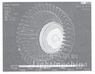
Set the natural convection heat transfer coefficient to 5w/(m2·°C), and use finite element calculation with ANSYS to obtain the steady-state temperature field distribution (Fig. 2). It can be seen that the maximum temperature of the spotlight is 79.4°C, and the temperature at the measuring point is 73.6. °C. According to the temperature of the heat sink fin measuring point, the heat transfer coefficient between the heat sink and the air is continuously adjusted. When the heat transfer coefficient is equal to 4.6 W/(m 2 · ° C), the calculated base temperature of the heat sink is consistent with the test result in the experiment. The heat transfer coefficient is the convective heat transfer coefficient of the air and the radiator at the time.

Figure 2 Temperature distribution of MR16 LED spotlights
3 Simulation results and data analysis
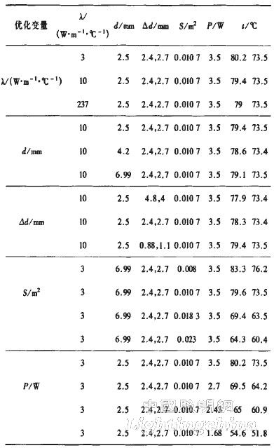
The MR16 LED spotlight heat sink optimization design involves variables such as heat flow power (P), heat sink base thickness (d), integrated chip pitch (Δd), and convection area (s). By changing these variables, the heat dissipation is optimized. Structure. Taking the temperature of the radiator fin to 60 °C as the index, the maximum heat dissipation power that can be achieved by the radiator is determined, and the heat dissipation capability of the entire system of the lamp is analyzed under the condition that other influencing factors are unchanged. The impact, the specific simulation analysis results are shown in Table 2.
Table 2 Radiator optimization design and analysis results

It can be seen from Table 2 that the thickness of the substrate is changed, the thermal conductivity of the thermal conductive adhesive between the substrate and the heat sink and the chip pitch, and the thermal conduction diffusion thermal resistance are small, which is not ideal for improving the heat dissipation effect of the MRl6 LED spotlight, the convection area of ​​the heat sink and the chip. Input power is the most important factor affecting the heat dissipation effect. The thickness of the substrate has an optimum value; the thermal conductive adhesive between the heat sink and the substrate should be selected according to actual conditions to save the cost of the lamp.
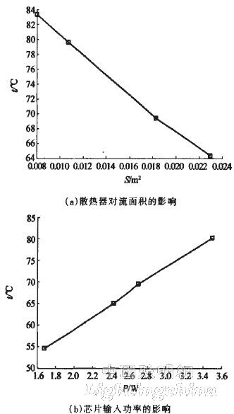
3(a) and (b) are graphs showing the effects of the convection area of ​​the heat sink and the input power of the chip on the heat dissipation effect of the spotlight according to Table 2, respectively.
It can be seen from Fig. 3(a) that the surface area of ​​the heat sink in contact with the air is increased, and the junction temperature of the LED drops sharply. When the convection area is equal to 0.0230mm2, the lowest temperature of the heat sink fin is about 60 °C, and the temperature gradient of the whole lamp is small, which fully exerts the best performance of the heat sink. According to the calculation, under the driving of l0V and 350mA, it is necessary to ensure that the surface temperature of the fins of the radiator is about 60 °C, and the convection area must reach 0.0233 m2 or more. It can be seen that when the input power is 3.5W, the main reason for the failure of the heat dissipation of the MRl6 LED spotlight by the heat sink is that the convection area of ​​the heat sink is too small.
It can be seen from Fig. 3(b) that when the input power of the lamp is 1.68w, the heat sink fin temperature is 51.8°C, the LED junction temperature is 54.6°C, the temperature gradient is small, and the lamp meets the heat dissipation requirement, but the heat sink does not fully play. Best performance. When the input power is 2.43W, the heat sink fin temperature is 60.9 ° C, and the chip temperature is 65 ° C. The lamp meets the heat dissipation requirements and also exerts the best performance of the heat sink. Therefore, when the input power of the lamp reaches about 2.5W, the existing heat sink performs its best performance.

Figure 3 mainly affects the effect of alizarin on the heat dissipation performance of spotlights.
4 Conclusion
Through the finite element simulation calculation of MR16 LED spotlight, the results show that the main factor affecting the heat dissipation capability of the heat sink is the contact area with air, and the chip pitch, substrate thickness, substrate and heat sink contact thermal resistance play a secondary role. Further analysis found that to achieve the best heat dissipation performance of the existing radiator, the input power must be about 2.5W, which lays a foundation for the further application of the structure radiator, and has important guiding significance for the production of high-power LED lamps.
Improving the heat dissipation capability of high-power LED lamps can be realized in many aspects. In terms of structural heat dissipation, the convection area of ​​the heat sink and the thermal resistance of the heat conduction will be two major directions to be considered. If necessary, the diffusion heat resistance should also be considered.
Edit: Cedar
USB C Adapters,Apple Usb Adapter,Wifi Usb Adapter for Pc,Wifi Adapter for Pc
Pogo Technology International Ltd , https://www.wisesir.net