In rural land security, the local government departments provide local image maps with low resolution and insufficient precision, which cannot be used as a working base map. In order to obtain a suitable image map of the scale, the low-altitude aerial photography technology of the UAV has become the most important means at present. The surveying and mapping drone can perform full coverage aerial photography with a resolution of 0.05 meters, select the ground control point for orthorectification, improve the geometric accuracy of the image, enhance the interpretability, and make the current situation strong, high precision and accurate positioning. : Orthographic image of 1000 scale.
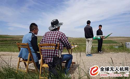
The surveying and mapping drone aerial photography team can be equipped with 2-3 people. After the aerial photography task is finished, the data will be checked. After passing the test, the subsequent data processing can be performed. In order to give readers a more intuitive experience, we went to Lanzhou, Gansu, to take pictures of the P700E UAV operation scene in the field, and detailed the operation process of mapping UAVs in rural land confirmation, hoping to benefit your work and study. .
1. Determine weather conditions
UAV aerial survey, the weather conditions are good or bad. Before starting the aerial photography, it is necessary to grasp the weather conditions of the day and observe the thickness of the clouds, the light and the visibility of the air.
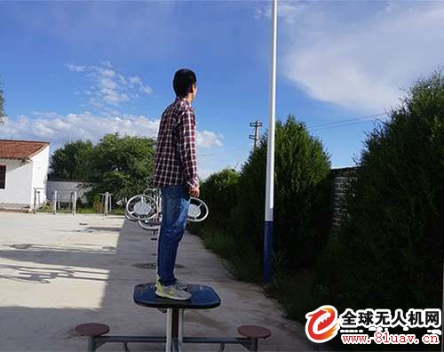
Observe the thickness of the cloud
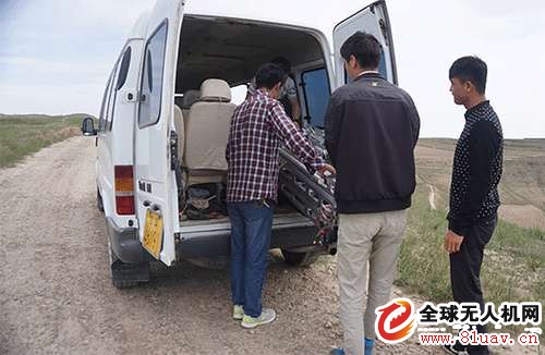
2. Arrive at the take-off location
After determining the weather conditions and cloud distribution for aerial photography, bring the drones, catapults, radio stations, computers and other related equipment to the aerial take-off point. The take-off point is usually inspected in advance, requiring a relatively flat site, no wires, high-rise buildings, etc., and the aerial order and sequence are determined in advance.
3. Determine the wind speed at the scene
After arriving at the scene, the wind speed was measured. The China P700E mapping UAV can withstand 6 wind speeds and adapt to temperatures between minus 20 ° C and 60 ° C.
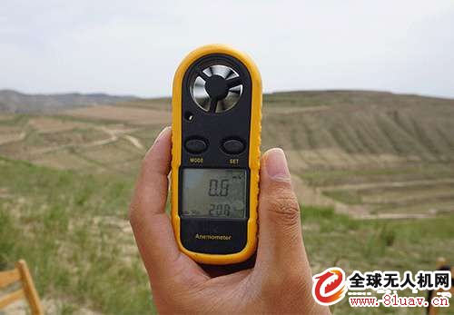
Measuring site wind speed
4, set up the catapult
In order to ensure the aircraft take off smoothly, the catapult is generally erected against the wind. The P700E adopts the configuration of the integrated ejection frame, which has small requirements on the site and strong adaptability to the terrain. Compared with other products, the design of the projectile rope is more convenient and quicker, and at the same time guarantees the safety of the operator to the greatest extent.

Erection of the ejection frame
5, set up a radio station
The radio is used for communication between the ground station and the drone. At this stage, most surveying and mapping drones use radio to exchange data between drones and ground stations. The high-frequency radio of P700E can conduct ultra-long-distance monitoring of up to 50 kilometers to ensure safe and efficient operation of the aircraft.
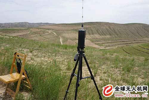
Set up a radio station
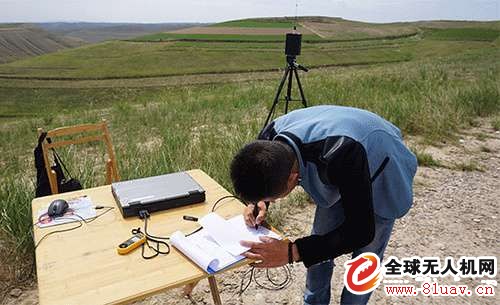
6, the day's job log
Record the wind speed, weather, takeoff and landing coordinates and other information on the day, and keep a reference for future data reference and analysis.
7, attitude angle adjustment
For departure points that are more than 200km from the last take-off location, the attitude and angle of the aircraft must be adjusted to ensure accurate communication. The drone machine is equipped with electronic compass, magnetic calibration and other equipment to ensure the self-attitude control of the aircraft during flight. Due to the different geomagnetic conditions, the P700E self-contained calibration system is used to deal with different geomagnetic conditions. Human-machine interference and safety hazards.
Determine control point coordinates and flight angle
8, the drone is placed on the catapult
During installation, it is necessary to check whether the components of the drone are tightly connected, whether the power supply wiring of the ejection frame is properly connected, and the power is sufficient.

Install drone to catapult
Antenk D-Sub,D-Shaped Connectors Solutions offer a broad range of higher reliability D-Sub connectors.
Antenk's D-Sub product line is designed for applications that require a rugged, robust I/O connector system with various styles and mounting options. All are used in a variety of industries including computer, industrial, medical, and military markets.
Antenk High-Density D-Sub Connectors
Available in cable mount options including crimp & solder cup and the board mount options including Dip Solder, Wire Wrap, High Profile, Right Angle, & Surface Mount (SMT). This comprehensive Antenk High-Density Density D-Sub product offering is available in both stamped & formed and machined contact options.
High density D-Sub connectors, for applications where the best possible contact density is required. Due to the [high" density of the 15, 26, 44, 62 and 78 contacts, this series is ideal for the most modern applications. The insulating body, a monoblock, complies with the UL94 V-0 standard. The contacts are machined and available in several quality classes.
Antenk Solder Type D-Sub Connector
Available in standard and high density versions
Supplied with stamped & formed or screw machine contacts.
Standard contact terminations accomodate up to 20 AWG standard wire
Available with white (nylon) or black (PBT) insulators. Standard shell plating is tin
Antenk D-Sub connectors solder cup machined contacts are manufactured according to the standards MIL-C-24308 and DIN 41652. The standard connectors from Antenk are available in all known versions and sizes. They are available in various version with numerous assemblies. The insulating body, a monoblock, complies with the UL94 V-0 standard. The contacts are machined and available in several quality classes.
Features of Antenk's Solder Cup Standard D-Sub Connector Machined contacts
Solder cup d-sub available in 5 industry sizes/positions
Standard Density (9 pin, 15 pin, 25 pin, 37 pin, 50 pin)
Tin shells have indents to provide grounding and additional retention.
Screw machine contacts offer high reliability. Non-removable contacts.
Optional mounting hardware available.
Materials of Antenk Solder Cup Standard D-Sub Connector Machined contacts
Shell: Steel, tin plated
Insulator: Glass-filled thermoplastic. U.L. rated 94V-O
(260°C process temp)
Machined contacts:
Male pins - Brass | Female pins - Brass
Plating: Gold flash on entire contact
Contact us for other plating options
Features of Solder Cup High Density D-Sub Machined Contacts
Solder cup d-subs in 4 industry sizes/positions
High Density (15 pin, 26 pin, 44 pin, 62 pin).
Approximately 65% more higher density then standard d-sub connectors.
Screw machined contacts offer high reliability.
Metal Shell provides EMI/RFI shielding. Available in 3 clinch-nut options.
Plug shells have indents to provide grounding & additional retention.
Connectors will fit in standard D-sub backshells.
Contacts will accept (28 - 24) gauge wire.
Materials of Solder Cup High Density D-Sub Machined Contacts
Shell: Steel, Nickel plated
Insulator: Glass-filled, PBT Thermoplastic. U.L. rated 94V-O
(230°C process temp)
Machined contacts: Brass, Gold Flash Plated(contact us for other plating options)
9 pin, 15 pin, 25 pin, 37 pin, 50 pin Male Solder Cup Standard D-Sub Connectors Machined Contacts, Solder Cup High Density D-Sub Machined Contacts,Female Solder Cup Standard D-Sub Connectors Machined Contacts
ShenZhen Antenk Electronics Co,Ltd , https://www.atkconnectors.com