When testing electronic devices, it is difficult to mention the versatility of the oscilloscope. In order to validate electronic circuits, engineers need to be able to view and measure the signals in their designs. Automated Test Equipment (ATE) typically does not provide extensive visual troubleshooting, which is a challenge for users who must install, calibrate, and troubleshoot the system. These operations require visualization tools that the oscilloscope can provide.
No other device offers more measurement tools than an oscilloscope. To implement oscilloscope functionality in an ATE environment, users typically use SFP (software front panel) oscilloscope software in the digitizer. However, although the software looks like an oscilloscope, it does not have the high-performance tools of a traditional oscilloscope and cannot be diagnosed.

Don Schoenecker, Vision Product Planner, Keysight Technologies
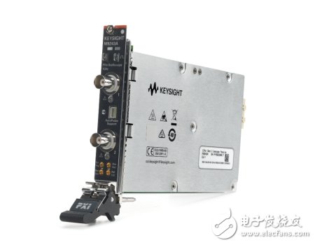
Delivers true desktop oscilloscope performance in a single PXI slotKeysight's latest M9241A (200 MHz), M9242A (500 MHz) and M9243A (1 GHz) InfiniiVision PXIe modular oscilloscopes are designed to provide the availability and performance of traditional benchtop oscilloscopes for PXIe modular systems. Keysight has more than 60 years of experience in manufacturing high performance oscilloscopes and has used this knowledge to create PXIe oscilloscopes that go beyond the simple combination of digitizers and oscilloscope software.

Figure 1: The Keysight M9243A is a 1 GHz, 2-channel oscilloscope with outstanding visualization and troubleshooting capabilities.
Keysight's M924XA modular oscilloscopes feature the superior MegaZoom technology, which is also used in the popular InfiniiVision 3000T X-Series benchtop oscilloscopes. They also have the same optimized user interface, so the experience of operating a M924XA oscilloscope on a computer is similar to using a familiar traditional oscilloscope.
Waveform visualization toolThe oscilloscope collects the data, processes it, and plots it on the screen for troubleshooting and signal analysis. This display also displays multiple waveforms superimposed on the screen at the same time. Using waveform strength allows for fast identification of signal errors, which is critical for observing signals. However, this is more difficult for users trying to use digitizers and oscilloscope software, and they are often plagued by signal display limitations.

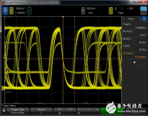
Figure 2: When a short pulse of several times per second occurs on a high frequency signal, a higher waveform update rate is required to capture and display this signal. Advanced triggering can be utilized to further isolate the signal.
Keysight's modular oscilloscopes eliminate these limits by providing industry-leading waveform update rates (up to 1,000,000 waveforms per second) to capture more signal detail. These oscilloscopes allow the user to create triggers based on the signal information displayed on the screen using zone triggering. When using zone triggering, if you can see the event on the display, simply draw a box on the screen with your mouse or finger (on the touch screen) and select the desired trigger action. This event is easily triggered.

Figure 3: Using a non-monotonic edge to isolate the signal, simply draw a box on the signal of interest and select “Must intersectâ€.
Reduce data collectionUsers often need to collect large amounts of data from digitizers running oscilloscope software because they do not have the ability to properly isolate the desired signals in real time. The large amount of data captured is transmitted to the controller for software analysis, hoping to capture the signal of interest.
The oscilloscope solves this problem by providing a set of tools that selectively perform data capture and centralized data acquisition and analysis based on advanced parameter information (short pulse, rise/fall time, setup and hold, etc.). This allows the user to isolate the signal of interest and then use measurement and analysis tools to determine the signal parameters of interest. Sometimes data is not needed at all, just identifying the event and counting it is enough to prove that it is the information you need.
Tool integrationWhile the oscilloscope feature is a prime feature of the Keysight M924XA Series modular oscilloscope, it is not the only analysis tool included with this instrument. The integrated 20 MHz arbitrary waveform generator provides excitation to activate the circuitry and operation of the system under test for the user to capture, edit, and play back signals. The waveform generator also provides a quick and easy way to integrate function generators to generate more standard signals.
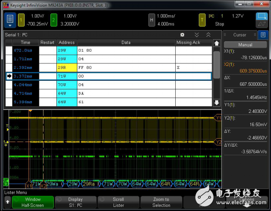
Protocol analysis tools are often difficult to integrate into a modular environment, but the M924xA family has this capability. It includes a number of advanced protocol tools for triggering and decoding serial communication signals. Whether it's chip-to-chip communication or military communications, its full-featured protocol analysis capabilities allow users to define packets of interest, trigger and decode communication protocols.

Figure 4: Decoding serial communications and analyzing events using advanced protocol analysis tools. Here we can see the CRC error count on the car CAN communication link.
As mentioned earlier, sometimes we only need to simply count the signal events. All oscilloscope trigger events can be easily converted to an event counter or accumulator. The universal counter can be used as an 8-bit frequency counter or as an event counter, providing a trigger function that is even faster than the display rate of up to 25 million events per second.
Waveform templateTemplate/limit testing is an important productivity tool for performing pass/fail tests according to specified standards in the manufacturing industry or for testing rare signal anomalies. In the past, ATE systems often required custom FPGA work to provide real-time analysis. Keysight's newest modular oscilloscopes feature powerful hardware stencil testing capabilities that can perform up to 270,000 tests per second. They also enable users to easily create templates based on previously captured "ideal" signals. They can then report the test results as a simple count or a six sigma performance benchmark.
DetectionGood signal analysis is only possible if the probe used to capture the signal is good. Keysight offers a wide range of probing solutions for modular environments, supporting a wide range of applications. In addition to standard passive voltage probes, Keysight has added high temperature environmental probes, high sensitivity current probes, high current probes, high voltage probes and power probes.
It is worth mentioning that the power supply probe has a large bias, low noise and 1:1 attenuation ratio, and the load is very low, which can be used for critical power integrity measurement.
The value of an oscilloscope in ATEATE operations often place a heavy burden on software programs (and programmers) when features are still in development or when performing proper analysis to characterize system performance. The oscilloscope is a versatile "universal" tool that can be used to verify system test configurations. Integrating the oscilloscope into an ATE system can further improve test operations. As a powerful tool, oscilloscopes can significantly improve system availability by improving calibration and troubleshooting interactions.
About Keysight
Keysight Technologies (NYSE: KEYS) helps customers bring breakthrough electronics and systems to market faster and at lower cost. From design to simulation to prototyping verification, production testing, and optimization in the network, Keysight offers a full range of electronic signal testing and analysis solutions. Our customers span the global communications, Internet infrastructure, aerospace and defense, automotive, semiconductor and general-purpose electronic terminal markets. In fiscal 2016, Keysight’s revenues reached $2.9 billion. For more information, please visit.
According to the different backlight sources, LCDs can be divided into two types: CCFL displays and LED displays.
Misunderstanding:
Many users believe that liquid crystal displays can be divided into LEDs and LCDs. To some extent, this understanding is misguided by advertisements.
The LED display on the market is not a true LED display. To be precise, it is an LED-backlit Liquid Crystal Display. The liquid crystal panel is still a traditional LCD display. In a sense, this is somewhat fraudulent. nature! South Korea`s Samsung was once convicted by the British Advertising Association as violating the country`s advertising laws because its [LEDTV" LCD TVs were suspected of misleading consumers. For liquid crystal displays, the most important key is its LCD panel and backlight type, while the LCD panels of displays on the market generally use TFT panels, which are the same. The difference between LEDs and LCDs is only their backlight types: LED The backlight and CCFL backlight (that is, fluorescent lamps) are diodes and cold cathode lamps, respectively.
LCD is the acronym for Liquid Crystal Display, which means "liquid crystal display", that is, liquid crystal display. The LED display refers to a type of liquid crystal display (LCD), that is, a liquid crystal display (LCD) with LED (light emitting diode) as the backlight source. It can be seen that LCD includes LEDs. Corresponding to the LED display is actually a CCFL display.
(1) CCFL
Refers to a liquid crystal display (LCD) with CCFL (cold cathode fluorescent lamp) as the backlight source.
The advantage of CCFL display is good color performance, but the disadvantage is higher power consumption.
(2) LED
Refers to a liquid crystal display (LCD) that uses LEDs (light emitting diodes) as a backlight source, and generally refers to WLEDs (white light LEDs).
The advantages of LED displays are small size and low power consumption. Therefore, using LEDs as a backlight source can achieve high brightness while taking into account lightness and thinness. The main disadvantage is that the color performance is worse than that of CCFL monitors, so most professional graphics LCDs still use traditional CCFL as the backlight source.
Lcd Module,Kortek Tft Lcd Monitor,Game Boy Color Tft Lcd Kit,A-Si Active Matrix Tft Lcd
ESEN Optoelectronics Technology Co., Ltd, , https://www.esenlcd.com