There are many factors that affect the stability of the CAN bus. The baud rate is a very important indicator. Many engineers have a headache when choosing the baud rate. Today we will talk about how to quickly solve the problem of special baud rate calculation.
The CAN bus uses asynchronous serial communication, that is, there is no separate clock line to ensure the clock consistency between the transceivers. Each transceiver divides the level on the bus according to the preset baud rate. . Therefore, the baud rate setting is very important for the stable communication of the CAN bus.
In the CAN bus, we can realize the communication of different baud rates by controlling the bit timing registers in the CAN node. In the CAN protocol, a bit time is divided into a sync segment, a propagation segment, a phase buffer segment 1 and a phase buffer segment 2. The length of each segment can be expressed in terms of an integer basic time unit, which is obtained by dividing the system's clock oscillator.
The sync segment is located at the beginning of a bit. CAN-bus specifies that the edge of the transition is a sync signal. However, there is a network propagation delay between the transmit node transmitting a bit and the receiving node receiving the bit, and the propagation segment is to compensate for this propagation. Delay, since the sampling point position is between the phase buffer segment 1 and the phase buffer segment 2, by setting the values ​​of the phase buffer segment 1 and the phase buffer segment 2, the sampling point position can be adjusted to ensure that each bit sampling point is consistent. The length adjustment range of the buffer segment is determined by the sync jump width (SJW).
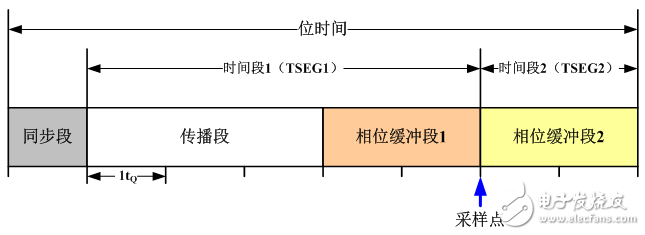
Figure 1 CAN bit time structure diagram
After a brief understanding of the segmentation of the CAN bus bit time, let's look at how the baud rate of a node is set. Figure 2 shows the CAN bit time characteristic register (CAN_BTR) of an ARM core. 
Figure 2 An ARM core bit time characteristic register structure
SILM (silent mode) and LBKM (loopback mode) are used for debugging;
SJW: synchronous jump width;
TS2/TS1: allocation of two time periods in bit time;
BRP: baud rate divider, which defines the length of the basic time unit;
For example, a famous car manufacturer's CAN communication standard stipulates that when the communication rate is 125 kbps, a single sampling should be used, and the sampling point position is set between 70% and 77%. The values ​​of the bit timing parameters can be seen in Table 1 and Table 2.
Table 1 LS_CAN communication rate and sampling point parameters
Table 2 LS_CAN optional time share and synchronous jump bandwidth

Sampling point: The sampling point can't be too far forward or too late. Otherwise, if it is just in the rising edge or falling edge of a bit, it will cause recognition error. Therefore, according to the CIA105 specification, the sampling point is suitable at around 87.5%. However, in general, we can choose between 75% and 85% according to the actual situation;
Synchronous jump width (SJW): The value of SJW directly affects the adjustable range of the phase buffer segment during resynchronization. The value of SJW can be selected between 1 and 4. We choose 3 and 4 to make the bus wider. Baud rate tolerance;
Number of sampling: divided into single sampling and three sampling. Although the sampling is designed to filter out the burrs on the bus at the beginning of the design, the use of three samplings often affects the SJW jump. Therefore, in practical applications, we usually use single sampling. .
After understanding the principle of setting the baud rate, we use ZLG Zhiyuan's baud rate calculation software to calculate the setting parameters of the 25kbps baud rate. The calculation result is shown in Figure 3.
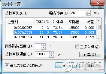
Figure 3 25kbps baud rate calculation parameters
According to the above mentioned principle, we select a set of parameters with a sampling point of 75%, SJW of 4, and a time share of 14, using ZLG's CAN card for verification.
Automatic baud rate identification: Using CANScope to automatically detect the baud rate function, the baud rate of the CAN card is recognized, and the recognition result is 25kbps;
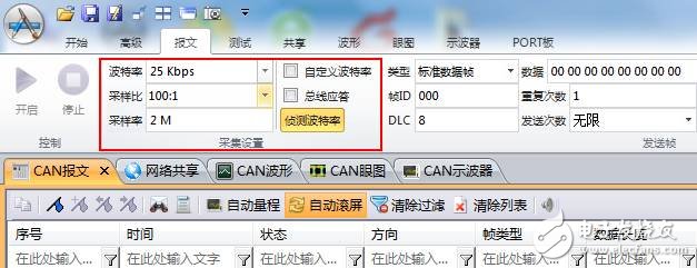
Figure 4 automatically detects the baud rate
Sampling point test: Using CANScope to test the sampling point of the CAN card at the current baud rate, the test result is 75%;
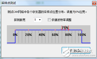
Figure 5 sampling point test
Bit width tolerance test: Using CANScope to test the bit width tolerance of the CAN card at the current baud rate, test its tolerance to the baud rate, the test result is 24kbps~26kbps, and the tolerance is better;
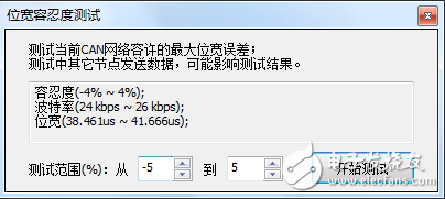
Figure 6 bit width tolerance test
Bit time test: Use CANScope's eye diagram function to test the bit time of the CAN card at the current baud rate. The bit time is 40us, which is consistent with the bit time of 25kbps baud rate.
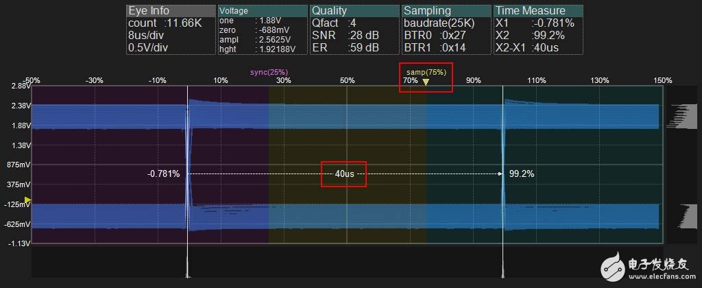
Figure 7 Eye test position time
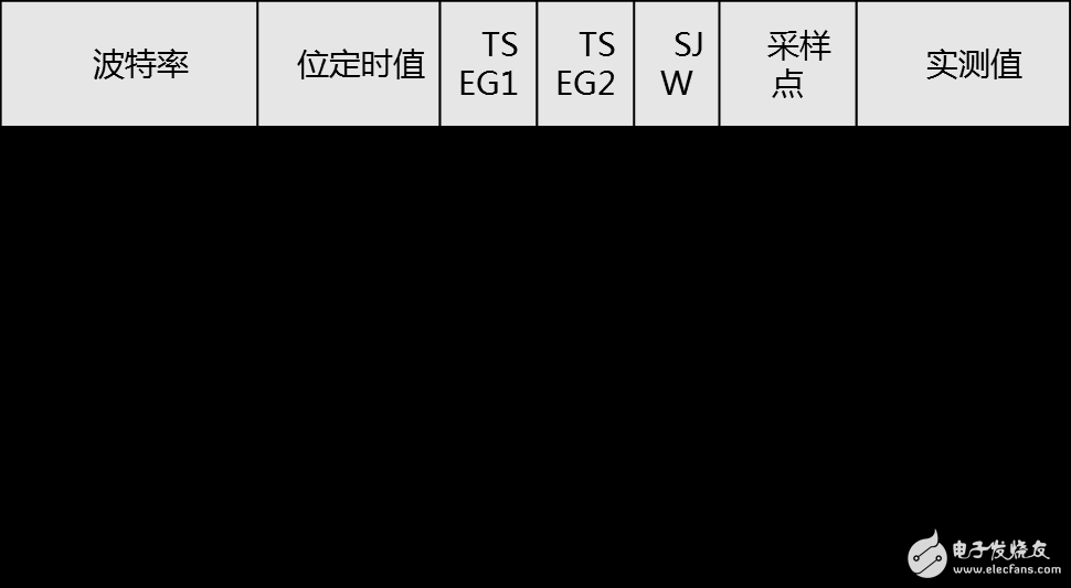
By verifying the baud rate register setting parameters calculated by the baud rate calculator, it is found that the test results are consistent with our expected results, so when using the special baud rate, we can quickly calculate by using the baud rate calculator. The parameter value of the bit timing register. Below we give some parameters for the special baud rate that can be referenced:
What is a fiber optic slip ring?
A fiber optic slip ring is a device that allows for the transfer of data, power, and signals between two rotating objects. The ring is made up of one or more optical fibers that are used to transmit light signals. These signals can be used to send power, data, or other signals between the two objects. The fiber optic slip ring is a newer technology that has many benefits over traditional slip rings.
How do fiber optic slip rings work?
A fiber optic slip ring is a device that allows electric current and optical signals to pass through a rotating joint. This is often used in applications where it is necessary to transfer data or power between two stationary points while the object rotates. The fiber optic slip ring uses light rather than metal to conduct these signals, which makes it ideal for use in high-speed or hazardous environments.
Types of fiber optic slip rings
When it comes to telecommunications, fiber optics are king. They're the backbone of almost every network today, and they're getting faster and more reliable all the time. That's thanks in part to a technology called fiber optic slip rings.
Advantages of fiber optic slip rings
A fiber optic slip ring is a device used in optical communication. It is a component of many fiber optic networks and it allows for the transmission of data over long distances without losing signal quality. Fiber optic slip rings are also used to improve the performance of other optical systems.
Disadvantages of fiber optic slip rings
Fiber optic slip rings are growing in popularity for rotating applications. Fiber optic slip rings provide many advantages over traditional electrical slip rings, including much smaller size, weight, and power consumption. However, fiber optic slip rings also have a few disadvantages. One disadvantage is that they can be more expensive than traditional electrical slip rings. Additionally, fiber optic cables are more fragile than electrical cables, so they can be more susceptible to damage.
Conclusion: What are the benefits and drawbacks of fiber optic slip rings?
When it comes to fiber optic slip rings, there are both benefits and drawbacks to consider. On the one hand, fiber optic slip rings offer a number of advantages over traditional metal contact slip rings. They are lighter in weight, which makes them easier to install and transport. They also generate less heat, making them safer to use in hazardous environments. Additionally, they provide superior performance in terms of electrical noise and signal integrity.
However, fiber optic slip rings also have some drawbacks. They are more expensive than traditional metal contact slip rings, and they can be more difficult to repair if they malfunction. Additionally, they may not be suitable for some applications due to their limited range of motion.
Fiber Optic Slip Ring,Brass Slip Ring,Fiber Optic Silp Ring,Electrical Rotary Joint
Dongguan Oubaibo Technology Co., Ltd. , https://www.sliprobo.com