design background:
In our design project, we will use clocks of 100M, 500M, etc. If our crystal oscillator cannot reach us, we will need to multiply the frequency. In the previous document, we learned about the frequency division, but how do we change the frequency multiplier? Here we It used altera's IP-based PLL.
Today we will learn to call and generate simple IP cores.
Design principle:
In this design, we call the IP core PLL to generate a 200M clock. Here we will learn and use a simple IP core.
Design architecture diagram:
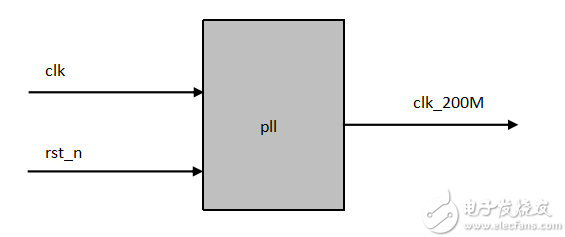
Design Flow:
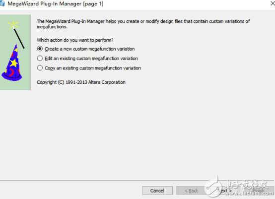
New project open tools, then select:

Then the following interface appears, the first sentence is to create a new IP core, the second opens you to establish so that we can modify, the third is to copy one, we choose the first choice, create one, and then the next step .
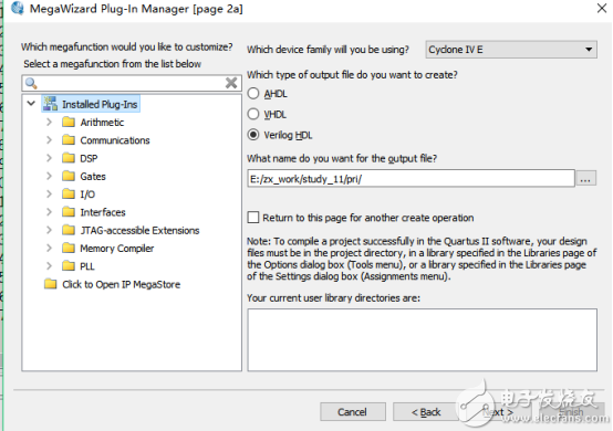
Then jump out of the following interface, we choose  Following
Then select our language verilog on the right, and then give us a name for the IP we built.
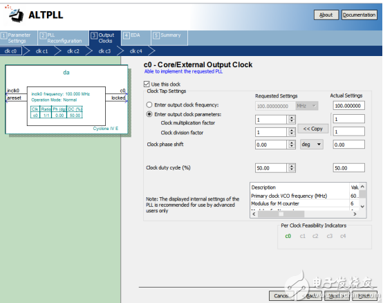
Then jump out of the following interface, inclk0 bit input we default to 50M, areset bit reset high effective, c0 bit output, locked bit output flag, and then enter our 100M to 50M, the next step.
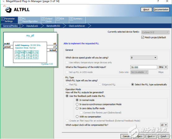
In order to see only the status of each pin, we do not proceed with the next step.

We can change how much our output clock is, we can change the phase of the output clock, the duty cycle, we write the output bit 200M, the duty cycle is 50%, then the next step.
After the next step, the following interface appears, click Finish to complete the establishment of the IP core.
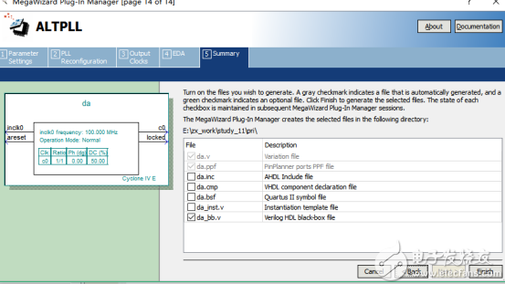
After that we open the generated IP core code and instantiate it.
Design code:
Design module
0 module pll(clk,clk_200M,rst_n,locked);
1 input clk;
2 input rst_n;
3
4 output clk_200M;
5 output locked;
6
7
8 my_pll my_pll_inst ( // Instantiate the IP core
9 .areset( ~rst_n ),
10 .inclk0( clk ),
11 .c1( clk_200M ),
12 .locked( locked)
13);
14 endmodule
Test module
0 `timescale 1ns/1ps
1
2 module pll_tb();
3 reg clk;
4 reg rst_n;
5
7 wire clk_200M;
8 wire locked;
9 initial begin
10 clk= 1'b1;
11 rst_n= 1'b0;
12 #200.1 rst_n= 1'b1;
13
14 #2000.1 $stop;
15
16 end
17
18 always #10 clk= ~clk;
19 pll pll_dut (
20 .clk(clk),
21 .rst_n(rst_n),
23 .clk_200M(clk_200M),
24 .locked(locked)
25);
26 endmodule
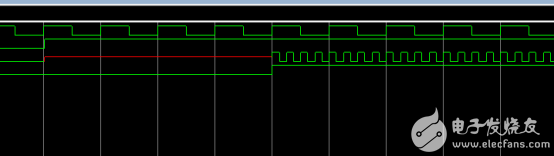
Simulation diagram:
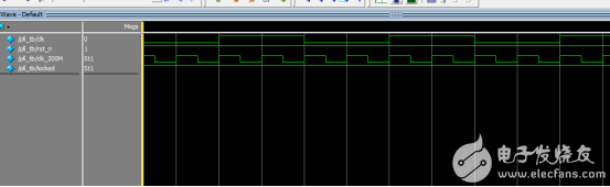
In the simulation we see that the clock we generate is 200M. Then we can use the flag generated by the phase-locked loop to reset the circuit with 200M clock, as follows:
Controller,video processor,led display controller
Guangzhou Chengwen Photoelectric Technology co.,ltd , https://www.cwstagelight.com