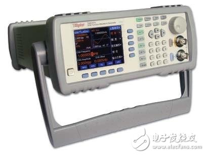
DDS (Direct digital synthesis) direct digital frequency synthesis is a new synthesis method of face rate synthesis directly from the phase concept. It introduces advanced digital processing theory and methods into the field of signal synthesis.
The DDS signal generator uses Direct Digital Synthesis (DDS) technology to increase the frequency stability and accuracy of the signal generator to the same level as the reference frequency, and can be fine over a wide frequency range. Frequency adjustment. The signal source designed in this way can work in the modulation state, and can adjust the output level or output various waveforms.

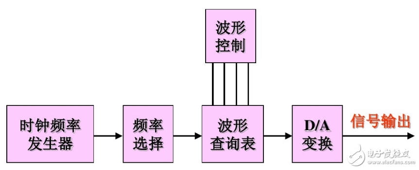
A full cycle of function waveforms is stored in the memory lookup table shown above. The phase accumulator tracks the current phase of the output function. In order to output a very low frequency, the difference phase (Δ) between the sampled samples will be very small. For example, a very slow sine wave will likely have a Δ phase of 1 degree. Then, the sample No. 0 of the waveform adopts the amplitude of the sine wave at the time of 0 degree, and the sample No. 1 of the waveform takes the amplitude of the sine wave at the time of 1 degree, and so on. After 360 samples, all 360 degrees of the sinusoid will be output, or exactly one cycle. A faster sine wave may have a Δ phase of 10 degrees. Thus, 36 samples will output one cycle of the sine wave. If the sampling rate remains constant, the frequency of the slower sine wave above will be 10 times slower than the faster sine wave. Further, a constant Δ phase must result in an output of a constant sine wave frequency. However, DDS technology allows the Δ phase of the signal to be quickly changed by a frequency meter. The function generator can specify a frequency table that includes segments consisting of waveform frequency and duration information. The function generator produces each defined frequency segment in sequence. By generating a frequency table, complex frequency sweep signals and frequency hopping signals can be constructed. DDS allows the phase of the function generator to change continuously from one level to another. Vector signal generators provide high flexibility and powerful solutions for scientific research, communications, consumer electronics, aerospace/defense, semiconductor testing, and emerging areas such as software radio, radio frequency identification (RFID), and wireless sensing. Network, etc. Some companies also offer many other analog output products that use DACs to generate analog signals. The basic architecture of the analog output board is to connect a small FIFO memory to a DAC. Most analog output boards are used to generate static voltages, and many can be used to generate low frequency waveforms.
DDS signal generator worksAccording to the Nyquist sampling theorem, this technique samples, quantizes, and encodes a sinusoidal signal from the phase Φ of the continuous signal, and then stores the formed sinusoidal function table in ROM/RAM. The frequency control word of the accumulator changes the phase increment, and different phase increments will result in different sampling points in one cycle. Because of the angular frequency ω=△φ·Δt, the phase/amplitude of this change can be quantized into a digital signal by changing the phase accumulator frequency control word without changing the sampling frequency, and then pass D/ The A-transform and low-pass filtering yields a phase-varying composite analog signal frequency. According to the Nyquist sampling theorem, this technique samples, quantizes, and encodes a sinusoidal signal from the phase Φ of the continuous signal, and then stores the formed sinusoidal function table in ROM/RAM. The frequency control word of the accumulator changes the phase increment, and different phase increments will result in different sampling points in one cycle. Because of the angular frequency ω=△φ·Δt, the phase/amplitude of this change can be quantized into a digital signal by changing the phase accumulator frequency control word without changing the sampling frequency, and then pass D/ The A-transform and low-pass filtering yields a phase-varying composite analog signal frequency.

The figure above is the basic block diagram of DDS, which is mainly composed of four parts:
The first part is a phase accumulator for determining the range and accuracy of the output signal frequency;
The second part is a sine function table (waveform memory) for storing the amplitude of the quantized and discrete sinusoidal functions;
The third part is D/A conversion, which can generate the required analog signal;
The fourth part is low-pass filtering, which is used to reduce quantization noise and eliminate waveform spikes.
The reference frequency source is a high-stability crystal oscillator that synchronizes the operation of the various components in the DDS. Therefore, the synthesized signal of the DDS output has the same frequency stability as the crystal oscillator. It can also be seen from the principle that it uses a highly stable fixed clock frequency to phase sample the signal to be synthesized. The larger the sample amount per unit time, the lower the synthesized frequency. The size of the sample is determined by the programmable frequency setting data.
DDS signal generator structure principleThe reference frequency clock is the operating frequency of the entire synthesizer. The input frequency word is stored in the frequency register 0 or 1. After the 32-bit phase is accumulated, it is added to the phase shift register to obtain the address of the internal ROM, and then passes through the internal ROM sinusoidal waveform. The table can obtain the corresponding amplitude value, and finally the synthesized sine wave is obtained by D/A conversion and low-pass filter. 3.189C52 and AD7008 interface design 3.3 orthogonal signal forming circuit design
The AD7008 is a monolithic DDS integrated chip with the structure shown in the figure. The device contains a 32-bit phase accumulator, a sine and cosine look-up table, and a 10-bit DAC DDS modulator with a clock frequency of 20 to 50 MHz. It also includes two 10-bit multipliers, a 20-bit IQMOD register, and a 12-bit phase register. . In addition to synthesizing sine waves, it also implements frequency modulation, phase modulation, amplitude modulation, and digital demodulation, as well as parallel and serial interfaces that interface with the microcomputer.

Since the phase accumulator of AD7008 is 32 bits, 2π=232, then △phase must be in the range of 0≤△phase≤232-1. For each clock cycle, 32-bit accumulator accumulates a phase step, output frequency fout For: fout=△phasefclock/232
Where fclock is the reference frequency. In actual use, the upper limit of fout is 40% of fclock (considering phase noise and spurious signal interference), that is, the upper limit of â–³phase is 0.4 & TImes; 232. â–³phase can be selected from FREQ0 and FREQ1 by controlling FSELECT. Although the AD7008 includes a 32-bit phase accumulator, its output is only 12 bits, so it is not necessary or possible to use 32-bit resolution. The 12-bit phase data is queried to convert to a 10-bit amplitude signal. If amplitude modulation is not required, the IQ multiplier can be bypassed (CR2 = 0) and the sinusoidal signal amplitude sent directly to the DAC circuit. The DAC full-scale output current can be adjusted by the external resistor Rset. The formula is as follows:
Iout(mA)=6233Vref(V)/Rset(Ω)
The KSPOWER brand 76W~100W DC adapters is one black or white color constant voltage mode, accepts universal input 100-240V AC voltage and provides the complete power transformers solutions covering the single output voltage ranging from 5Volt to 36Volt and the output current ranging from 100ma to 8000ma. The ac dc power adaptor follows high quality level VI energy efficiency and meet IEC/EN/UL 62368-1 safety standard, with UL/cUL CE FCC KC KCC TUV GS RCM CCC SAA C-Tick UKCA RoHS CB PSE PSB safety certificates export for global countries. The limited power source is Class I and Class II power designed with the standard AC outlet of IEC320-C14, IEC320-C6, IEC320-C8 and offers 3 years after-sale customer service. The external ac power adapter accepts various dc connector size for various audio/video and I.T.E applications and protections for short circuit, over load, over voltage and over temperature with green indication light for power on.
power adaptor, dc power adapter, dvr adapter, limited power source, power transformers
Shenzhenshi Zhenhuan Electronic Co., Ltd , https://www.szzhpower.com