Capacitive sensors typically convert the measured change into a change in capacitance. At present, various types of sensors based on this principle have been widely used in measuring acceleration, liquid level, geometric aperture and the like. However, sensors with varying capacitance (especially MEMS sensors) often have a capacitance variation of only a few pF or even a few fF. This puts high demands on the accuracy of capacitance detection. Especially in the development of sensors, it is often necessary to test and calibrate the sensors with extremely high precision capacitance detection equipment. However, there has been a lack of special instruments for real-time detection of tiny capacitors at home and abroad. It is common practice to design and manufacture special capacitance detection circuits for the developed sensors, which undoubtedly increases the difficulty and workload of the sensor design. In response to this problem, we designed a general-purpose capacitive sensor detection system. The system can detect tiny capacitors in real time, and can realize real-time display and storage functions through the host computer.
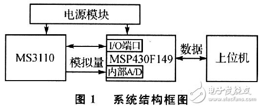
1 overall designThe detection methods of the capacitive sensor mainly include: designing a dedicated ASIC chip; using discrete components to achieve measurement through a capacitor bridge, frequency measurement, etc.; using a general capacitance detecting chip to convert the capacitance into a voltage or other amount. Considering technical difficulty, measurement accuracy and other aspects, the system uses integrated capacitance detection chip to complete the detection of capacitive sensors. The system structure block diagram is shown in Figure 1. The capacitance detection chip uses the MS3110 from Irvine Sensor. The MS3110 converts the capacitance to a voltage output (range 0 to 10 pF). The integrated 12-bit A/D converter of the MSP430F149 samples the output voltage and sets the internal registers of the MS3110 through the I/O port. After being sampled, the data is transmitted to the host computer through the serial port for processing, real-time display, storage, and the like. The upper computer is composed of an ordinary microcomputer.
2.1 MS3110 Introduction and Register Settings
The MS3110 is a general-purpose capacitance detection chip manufactured by Irvine Sensor with extremely low noise. It uses CMOS technology, the operating voltage is +5 V, the measurement sensitivity is, and the integrated compensation capacitor and other parameters can be controlled by registers. The basic measurement principle is: charging and discharging the measured capacitor and the reference capacitor at the same time, and converting the measured capacitor and the reference capacitor into a voltage output through current integration, low-pass filtering, amplification, and the like. The MS3110 contains a 60-bit register and a 100-bit EEPROM. The EEFROM can be programmed by the I/O port of the MSP430F149, or the MS3110 can be programmed in the test state. These settings allow precise adjustment of the parameters of the various modules within the MS3110.
The block diagram of MS3110 is shown in Figure 2. The MS3110 is mainly composed of a capacitor compensation circuit, a charge integration circuit, a low-pass filter, and an operational amplifier.
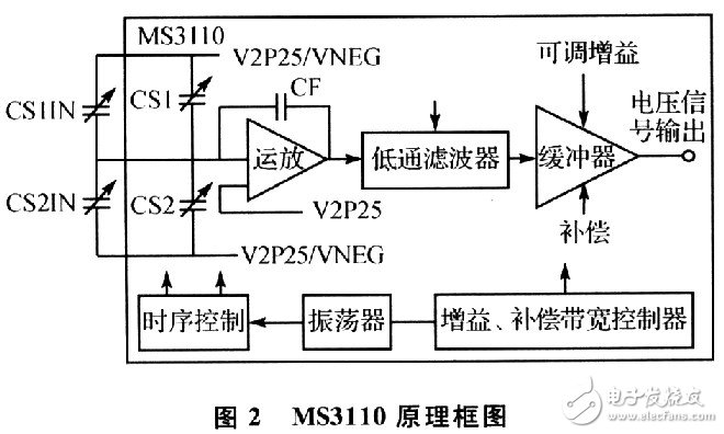
Among them, CSlIN and CS2IN are the detected capacitors, and CS1 and CS2 are the adjustable capacitors inside the MS3110. By setting the internal registers, CS1 can be adjusted from 0 to 1.097 pF, and CS2 can be adjusted from 0 to 9.709 pF. CF is the integral capacitance of the charge integrator and can be adjusted from 0 to 19.437 pF. The adjustment steps of the above three adjustable capacitors are all 19 fF. The bandwidth of the low pass filter can be at O. Adjustable in the range of 5 to 8 kHz, the adjustable gain GAIN can be selected as 2 or 4.
In addition, the reference voltage VREF, the no-load output voltage Vout, and the like can also be accurately adjusted by registers. The calculation formula of its no-load output voltage is as follows:
Vout=GAIN&TImes;V2P25&TImes;1.14&TImes;(CS2T-CS1T)/CF+VREF (1)
Where: CSlT=CS1IN+CSl, CS2T=CS2IN+CS2; the adjustable internal gain GAIN of this system is 2; V2P25 is the chip reference voltage output, the default value is 2.25 V; the reference voltage VREF is optional. 5 V and 2.5 V two values, select O. in this system. 5 V. Since the programming of the EEPROM requires an additional 16 V, the TEST pin is pulled low in this system to put the chip in a test state, and its registers can be directly changed by I/O. Since the register data will be lost after power-down, all registers need to be initialized after each power-on. It is important to note that in the write register timing diagram given in the MS3110 data sheet, the data input clock SCLK period is marked as a fixed value of 2 μs. In the experiment we found that the cycle can be successfully set when the period is more than 2μs.
2.2 MSP430F149 Introduction and Communication Interface Design
The system uses the MSP430F149 integrated 12-bit A/D converter for A/D conversion. When the MSP430F149 is operated at a clock frequency of 1 MHz, the current of the chip is about 200 to 400 μA; in the standby mode, the power consumption is only O. 7μA; in power-saving mode, the current can be as low as 0.1 μA. The integrated 12-bit A/D converter has a high slew rate of up to 200 kbps, making it ideal for most data acquisition applications, providing great convenience for system-wide single-chip solutions.
The MSP430F149 integrated A/D converter can use the internal 2.5 V reference voltage or an external reference voltage, but its internal reference voltage accuracy is poor. In this system, the MS3110's 2.25 V reference voltage output is used as the A/D. The reference voltage of the converter. The use of low-power microcontrollers and integrated A/D converters ensures low system power consumption.
The communication interface with the host computer adopts the serial interface integrated with MSP430F149, and is directly connected to the serial port of the computer through the conversion of the MAX3232 chip to the three-wire RS232 interface.
3 system software designThe system software includes two parts of the single chip software and the upper computer software.
3.1 SCM software design
Using the IAR Assembler for MSP430 integrated development environment, the program of the MCU part is written in C language, including system initialization, measurement chip register initialization, measurement and data transmission. The software flow of the single chip microcomputer is shown in Figure 3.
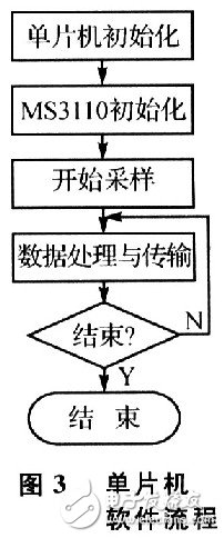
The initialization of the MCU includes the initialization of the MCU I/O, the initialization of the serial port parameters, the initialization of the A/D converter, and the communication system parameters with the host computer. The MS31lO initialization is to initialize the internal registers of the MS3110 through the MCU I/O, including reference capacitor values, adjustable gain, initial voltage and other parameters. After the sampling starts, the MCU samples according to the set sampling rate; after the sampling is finished, the data is converted and transmitted to the host computer for processing, display and storage.
3.2 PC software design
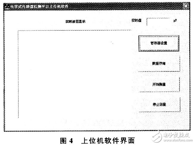
The system software of the system is written by VC++6.0 software and C++ language. The software functions mainly include setting parameters, communicating with the lower computer, real-time graphical display, storage and reading of data. The upper computer software interface is shown in Figure 4.
The initial output of the circuit should be calibrated prior to testing. The method is as follows: Set CS1 and CS2 to O, and use the high-precision voltmeter to measure the output voltage of the MS3110 chip, and the output is O. 497 192 V, the VREF in equation (1) is corrected to 0.497192 V.
Solder a 1.8 pF multilayer ceramic capacitor on the CS2IN board to simulate an external capacitive sensor; the internal adjustable capacitor CS2 is stepped from O to 342 fF to simulate the change in sensor capacitance, step value It is 19 fF. The specific register parameters are set as follows: CSl is set to O, set to 9.728 pF for CF, adjustable gain GAIN is set to 2, V2P25 is set to 2.25 V, and other parameters are taken as recommended by the manual. It was experimentally determined that when CS2 was taken as O, the measured value was 1.960 021 pF. The difference from the nominal value of the capacitor is mainly caused by the tolerance of the capacitor itself and the step capacitance of the circuit. From formula (1):
CS2=(Vout-VREF)CF/(GAIN&TImes;V2P25×1.14) (2)
Substituting specific values ​​can be obtained:
CS2=(Vout-0.497 192)×9.728/5.13 (3)
Among them, Vout = (A / D sample value / 4 095) × 2.25. The results of the precision test experiment are listed in Table 1 (the measured capacitance is the mean of 10 measurements).
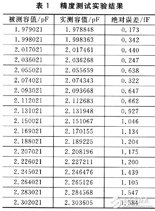
The test results show that the capacitive sensor detection system has high detection accuracy, the average error is only 0.879 fF, and the maximum absolute error is less than 1.6 fF. Since the integrated A/D converter of the MSP430F149 is 12 bits, when the CF takes 9.728 pF, the resolution of the system to the capacitor is only 1.042 fF. It can be seen that the resolution of the A/D converter is an important factor that limits the detection accuracy. A higher number of A/D converters can be considered when making improvements to the system.
ConclusionIn this paper, a capacitive sensor detection system is designed based on the capacitance detection chip MS3110, and the design points and problems needing attention are given. The system has high test accuracy and can be used for capacitive sensor detection and development.
USB charger, USB Adaptor, Charging USB Ports, USB quick charger
NINGBO COWELL ELECTRONICS & TECHNOLOGY CO., LTD , https://www.cowellsocket.com