High-power millimeter-wave sources are the core components of the launch front in millimeter-wave radar, communications, jammers, and precision weapon guidance systems. Solid-state devices have received much attention due to their low DC voltage, high reliability, strong impact resistance, compact circuit structure, small size, and light weight. However, as the frequency increases, the power output of a single solid-state device will rapidly decrease, making it difficult to meet practical application requirements. The power synthesis method that combines the output powers of multiple coherently working solid-state devices or superimposes multiple discrete devices is an effective method for increasing the output power of a millimeter wave system, and has been widely used.
This paper proposes a waveguide-based four-way spatial power synthesis network. This structure can well ensure that the power equal amplitude is in-phase and quadrature. At the same time, using the waveguide as input and output can reduce losses when outputting high power energy. Simulation results using three-dimensional electromagnetic simulation software HFSS show that in the range of 31GHz-38GHz, the four-way amplitude imbalance of the power division network is less than 0.05dB, the phase is also well consistent, and the return loss at the input end is less than -20dB. The return loss of the input and output ends of the entire synthetic network is also less than -12dB, and the insertion loss is less than 0.6dB.
2 power divider designThe basic structure of a waveguide-based four-way power splitter is shown in Fig. 1. Since the T-junction power distribution network itself is not matched, appropriate matching elements need to be placed at the branch joints to adjust the matching of each port. In this paper, a matching discontinuity structure is added at the branch joint. Changing the structure can adjust the center frequency and bandwidth of the power distribution network. Since the power divider is symmetrical, the four output ports have the same amplitude and phase.
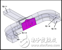
Figure 1 four-way power distribution structure
The result of power splitter simulation through HFSS is shown in Figure 2:
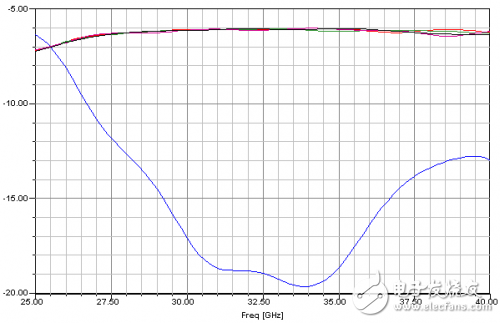
(a) Magnitude
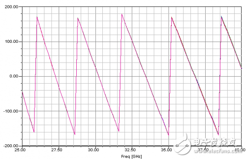
(b) Phase
Figure 2 Simulation result of power divider
As can be seen from Figure 2, the four-way power divider can achieve power distribution in a wide frequency band, and the input port return loss is less than -15dB. At the same time, due to the symmetry of the power division network, its phase consistency is very good.
3 Power Synthesis Network DesignThe probe-waveguide-microstrip transition is the most widely used transition structure in millimeter-wave planar integrated circuits. According to the relationship between the plane of the microstrip circuit and the propagation direction of the wave in the waveguide, it can be divided into two structural forms, one is micro The plane of the band circuit is perpendicular to the propagation direction of the wave in the waveguide, as shown in Fig. 3; the other is that the plane of the microstrip circuit is parallel to the propagation direction of the wave in the waveguide, as shown in Fig. 4.
This article adopts the structure of the microstrip plane and the wave propagation direction shown in FIG. 4 to realize the Ka-band waveguide-microstrip transition. In this structure, a coupling microstrip probe is used to couple the electromagnetic field in the waveguide into the microstrip and pass through a high-impedance line to the 50Ω microstrip line. The appropriate coupling size is used to reduce the influence of the microstrip circuit on the internal electric field of the waveguide.
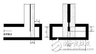
Figure 3 Microstrip plane perpendicular to wave propagation
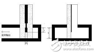
Figure 4 The microstrip plane is parallel to the wave propagation direction
The four-way power synthesis network model is shown in Figure 5:
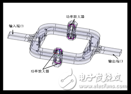
Figure 5 Model of a four-way power synthesis network
First, a four-way equal power distribution network divides the waveguide energy equally into four-way reduced waveguides, and then transitions through a waveguide-microstrip probe to achieve power synthesis via a four-channel power synthesis network. The simulation results are shown in Figure 6:
As can be seen in Figure 6, in the frequency range of 31 GHz-38 GHz, the return loss of the input and output ports of the synthetic network back-to-back simulation is less than -12 dB, and the insertion loss is less than 0.6 dB.
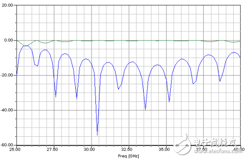
Figure 6 Power Synthesizer Simulation Results
4 ConclusionIn this paper, a waveguide-based four-way spatial power distribution/synthesis network is proposed for the millimeter wave band. The network uses rectangular waveguides as input and output ports for power distribution/synthesizing through a four-power distribution structure. The HFSS software simulation and optimization, the structure shows a very low insertion loss and return loss, is a useful power synthesis structure.
Auto Radiator,Car Radiator,Car Coolant,Car Engine Coolant
Huangshan Kaichi Technology Co.,Ltd , https://www.kaichitech.com