The following is the circuit diagram of [start-stop control circuit for single-button multi-motor]
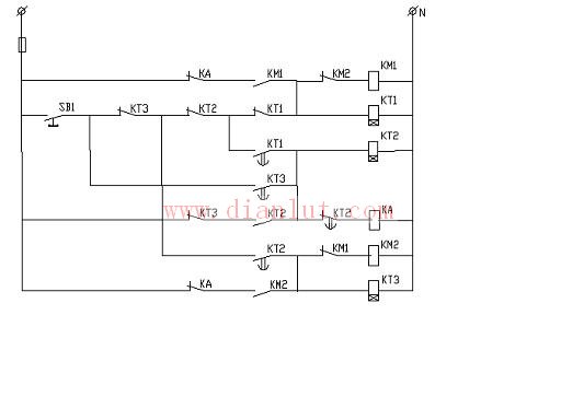
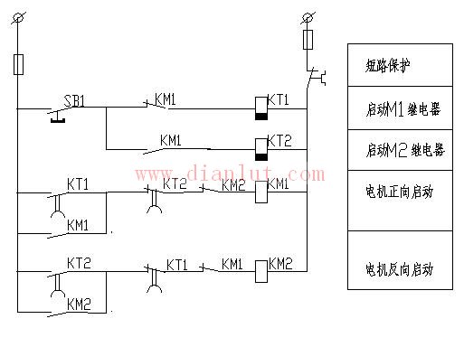
1. There is a time relay forward, stop, reverse cycle start-stop control
1) The first time æ¿ SB1, KM1 is powered and self-locked by the normally closed contacts of KT1, KT2, KT3 and KM2, and the motor is started in the forward direction; before KT1 is also energized, its normally closed contact is open, normally open The contact delay is closed, and the circuit is prepared for the second æ¿SB1.
2) The second time æ¿SB1, KT2 and KA are energized and self-locked by the normally closed contacts of KT1 and KT2, and the normally closed contact of KA is disconnected from KM1, and the motor stops. KT2 delays to, in addition to the start circuit to convert, but also for the third æ¿ SB1 to prepare the circuit; also makes the KA coil circuit disconnected and lose power, KA's normally closed contact resumes closing, is KM2 self-locking Prepare the circuit.
3) For the third time, SB1 can only make KM2 and KT3 energized and self-lock through the normally closed contact of KT3, and the motor will start in reverse; KT3 delay time to implement circuit conversion, prepare circuit for the 4th æ¿SB1.
4) For the fourth time, SB1, KT2 and KA are energized and self-locked by the normally closed contact of KT3. The normally closed contact of KA is disconnected from KM2, and the motor stops. One cycle is completed, and after the fifth time, æ¿SB1 repeats the action of items 1 to 4.
One cycle is completed, and after the fifth time, æ¿SB1 repeats the action of items 1 to 4.
The related pictures of this topic are as follows, click on the picture to see the big picture:
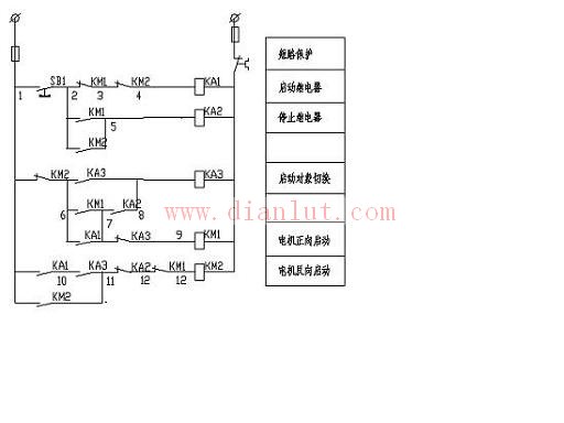
2. No time relay forward, stop, reverse cycle start-stop control
When the button is pressed 4 times, the circuit works as follows:
The first time æ¿SB1, the KA1 is powered by the KM1(2-3)-KM2(3-4) contact; and the KM2(1-6)-- KA1(6-7)-KA3(7-9) The KM1 is powered and self-locking, and is activated in the forward direction, and simultaneously switches the start/stop signal path.
The second time æ¿ SB1, the KA2 is powered by the KM1 (2-5) contact; the KA3 is obtained by KM2(1-6)-- KM1(6-7)-KA2(7-8)
The electric motor is self-locking and the starting object is switched at the same time; KM1 loses power due to the disconnection of KA3 (7-9) in the energizing circuit, and stops in the positive direction.
The third time æ¿SB1, KA1 is powered by KM1(2-3)-KM2(3-4); KM1 will not be re-opened due to the disconnection of KA3(7-9)
Get electricity; pass KA1(1-10)--KA3(10-11)
-- The path of KA2(11-12)--KM1(12-13) enables KM2 to be powered and self-locking, reverse-starting, and at the same time switch the start/stop signal path.
The fourth time æ¿ SB1, KA2 is powered by KM2 (2-5); since KM2 (1-6) is disconnected, although KA2 (7-8) is turned on, KA3 cannot be recharged. Instead, KA2 (11-12) disconnects the coil circuit of KM2 and de-energizes it, stopping in reverse.
One cycle is completed, and after the fifth time, æ¿SB1 repeats the action of items 1 to 4.
The biggest disadvantage of the circuit is that it can only be started and stopped in sequence.
Whether the switching of the start-stop signal will cause the power-rush phenomenon due to improper operation, and it needs to be verified in practice.
The related pictures of this topic are as follows, click on the picture to see the big picture:
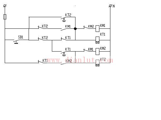
3. Positive-reverse cycle (no stop) start control
The line composition is equivalent to the direct forward and reverse start mode of the interlocking of the three buttons of the forward and reverse buttons.
The following figure uses an electric delay relay as the starting circuit of the circuit conversion component;
In the lower middle picture, an intermediate relay is used as the starting circuit of the circuit conversion element, and the operation of the circuit may cause an abnormal phenomenon due to unskillful operation.
The following figure is based on the middle figure. The intermediate relay is changed to the circuit of the start-up component using the loss-of-delay relay to ensure sufficient turn-on and full disconnection. Compared with the middle picture, it is not so easy to make mistakes. .
The comparison between the upper and lower diagrams shows that the number of components and contacts used is the same, and the same purpose can be achieved, but the concept of composing the circuit is different, and you can analyze it.
The related pictures of this topic are as follows, click on the picture to see the big picture:
The related pictures of this topic are as follows, click on the picture to see the big picture:
The related pictures of this topic are as follows, click on the picture to see the big picture:
4. 3 motor cycle start (do not stop) control
1). Below is the electrical principle of time relay
The first time æ¿ button SB1, through the normally closed contacts of 3KT1, 2KT1 and 1KT1, the 1K1T and 1KM1 are simultaneously powered and self-locked, and the M1 motor is started;
The second æ¿ button SB1, through the normally closed contacts of 3KT1, 2KT1 and the normally open contacts of 1KT1, enables 2KT1 and 2KM1 to be simultaneously powered and self-locking, starting the M2 motor, and stopping the M1 motor at the normally closed point of 2KM1;
The third button SB1, through the normally open contacts of the 3KT1 normally closed contacts 2KT1 and 1KT1, enables the 3KT1 and 3KM1 to be powered simultaneously and self-locking, starting the M3 motor, and simultaneously stopping the M2 motor at the normally closed point of 3KM1, starting the M3 motor; The fourth button SB1 stops the M3 motor and starts the M1 motor.
After each button SB1 is pressed, one motor is stopped and one motor is started, so that it is cycled.
2) The lower middle picture shows the electrical principle of no time relay
The working situation is:
The first time æ¿ button SB1, the KA1 is energized by the normally closed contacts of KM1 and KM2, KM1 is also powered and self-locking, the first motor is started, and the coil circuits of KA1 and KA2 are simultaneously converted;
The second æ¿ button SB1, the KA2 is energized by the normally open point of KM1, the normally closed contact of KM2 and KM3. On the one hand, KM1 is disconnected, the first motor is stopped, and on the other hand, KM2 is powered and self-locking. The second motor is started, and the coil circuit of KA1 and KA2 is cut off, and the coil circuit of KA3 is turned on;
The third æ¿ button SB1, the KA3 is powered by the normally open point of KM2 and the normally closed contact of KM3. On the one hand, KM2 is disconnected, the second motor is stopped, and on the other hand, KM3 is powered and self-locking. Three motors are started, and the coil circuits of KA2 and KA3 are cut off, and the coil circuit of KA1 is restored.
After each button SB1 is repeated, the first to third operations are repeated, one motor is stopped, and one motor is started, so that the cycle is endless.
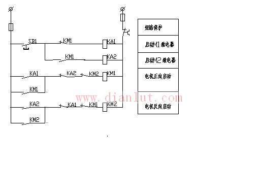
3) The following figure shows the simplified electrical principle of the middle figure
The working situation is:
The first time æ¿ button SB1, the KA1 is energized by the normally closed contact of KM1, KM1 is also powered and self-locking, the first motor is started, and the coil circuits of KA1 and KA2 are switched at the same time;
The second æ¿ button SB1, the KA2 is powered by the normally open contact of the KM1. On the one hand, the KM1 is disconnected, the first motor is stopped, and on the other hand, the KM2 is powered and self-locked, and the second motor is started. Continue to turn on the coil circuit of KA2;
The third æ¿ button SB1, through the normally open point of KM2 and the normally closed contact of KM1, makes KA1 and KA2 energized at the same time. On the one hand, KM2 is disconnected, the second motor is stopped, and on the other hand, KM3 is powered and The lock, the third motor is started, and the coil circuit of KA1 is restored.
After each button SB1 is repeated, the first to third operations are repeated, one motor is stopped, and one motor is started, so that the cycle is endless.
Try comparing the two figures, which is more reasonable.
The related pictures of this topic are as follows, click on the picture to see the big picture:
The related pictures of this topic are as follows, click on the picture to see the big picture:
The related pictures of this topic are as follows, click on the picture to see the big picture:
5. 3 motor cycle start-stop control without time relay
The related pictures of this topic are as follows, click on the picture to see the big picture:
6.4 Start-stop control of any one of the motors
1) The following figure shows the control principle of starting and stopping any motor.
2) KM1, KM2, KM3 and KM4 activate the respective motors M1, M2, M3 and M4, respectively, and KA is the stop relay.
3) KT time setting is greater than KT0, KT0 needs to be greater than 3S--human reaction time.
4) Start the one, just press the button SB1, and when the indicator light of the one is on, you will let go and it will be correct. This is because after the KT0 delay has elapsed, the circuit will switch before the KT delay, which will disconnect the circuit that was previously started and turn to the next one.
5) The cycle start-stop control of the 4 motor is to remove the time relay KT0 and its corresponding link in the above figure.
7 3 motor start and stop control
1) This is the control method of the conveyor belt. The schematic diagram is as follows:
2) KM1, KM2 and KM3 control motors M1, M2 and M3, and KA is the stop relay.
3) KT1 and KT2 are time-delay stop time relays, which are specially designed for conveyor belts, and KT3 is used for circuit conversion.
The related pictures of this topic are as follows, click on the picture to see the big picture:
8. One-button multi-motor relay-contactor start-stop control is summarized as follows. If there is something wrong, please give corrections and supplements to friends, peers and seniors.
1) Because it is a control button, to start multiple motors, you must have a conversion circuit. At the same time, in order to be safe and reliable, the circuit must be switched instantaneously and delayed.
2) For each additional control of a motor, a set of conversion circuits is required.
3) The more functions that are controlled, the more complicated the control circuit is, and the more electrical components are used. Such as: loop start / stop, than a pure cycle start more than a 'stop' signal link; start any one, than the cycle start / stop and a layer of choice, the natural circuit is more complex, composed of these There are more electrical components in the circuit.
4) It is not known how much of these single-button multi-motor relay-contactor start-stop control circuits will be used in actual production. I have never encountered the design, construction and maintenance process of my own for many years. Dear friends, peers and seniors, what about you?
Zhejiang Best Nail Industrial Co., Ltd. , https://www.beststaple.com