Keywords: photoelectric medium conversion chip optical transceiver module RJ45 magnetic module
1 The choice of optoelectronic media conversion chip Optocal & Electronic Media Converter (OEMC) is the core of the entire transceiver. It directly determines the functional characteristics, price, grade and other components of the optical transceiver. The choice of OEMC is The first step in fiber optic transceiver design is also the most important step.
The main performance indicators of OEMC are:
(1) Transmission rate Currently, the transceivers on the market mainly have two transmission rates: 100Mbps and 10 / 100Mbps adaptive. The former only supports 100Mbps transmission rate, the advantage is that the number of pins is small, wiring, management functions and status indicators are simpler, and the cost is low, but its application is not as flexible as the latter, and can only be used in environments where the transmission rate of both ends of the device is 100Mbps. Medium, so it is often used in backbone networks. On the basis of the former, the latter can also be used in an environment with a large number of 10BASET systems: it can not only use the 100BASET system, but also smoothly transition the 10BASET system to the Fast Ethernet environment, which maximizes the protection of user investment. There are generally two ways for OEMC to achieve 10 / 100Mbps: one is through a hardware jumper, and the other is to change the settings of internal registers by external programmable chips.
(2) Full-duplex / half-duplex performance Generally, the backbone network is full-duplex, and the user end mostly uses half-duplex. Accordingly, the transceiver is divided into three types: full-duplex, half-duplex, and full-duplex / half-duplex adaptive automatic conversion. Full-duplex transceivers are often used in backbone networks, half-duplex is mostly used in user access networks, and the third type can be used flexibly in the backbone network and can also be used in user access systems. It only needs to be cheap on the user side. Half-duplex hub, the networking cost will be greatly reduced. There are generally two ways for OEMC to achieve full-duplex / half-duplex adaptive automatic conversion: one is to change the setting of internal registers through hardware jumpers or external programmable chips, and the other is that OEMC itself can automatically recognize the speed of the media signal, and Realize adaptive automatic conversion. Therefore, it is ideal to choose the latter OEMC, which can not only simplify the design process, but also adapt to market needs, and it is convenient for users to upgrade.
(3) Network management function Network management is a guarantee of network reliability and a way to improve network efficiency. The functions of network management such as operation, management, and maintenance can greatly increase the available time of the network and increase the utilization rate of the network. Network performance, service quality, security and economic benefits. However, the manpower and material resources required for the development of optical fiber transceivers with network management functions far exceed those of similar products without network management. The main performances are:
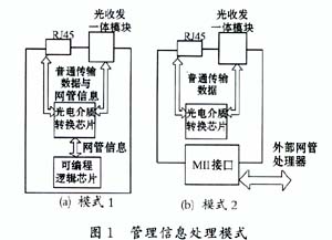
1) There are two ways to implement the network management function of the hardware investment transceiver: One is to configure the network management information processor on the transceiver circuit board-a programmable logic chip to process the network management information. The chip uses the bidirectional management instructions on the OEMC Interface (Managenent Data Input / Output, MDIO), management data synchronous clock input interface (ManagenentData Clock, MDC) and managed information input / output pins and other interfaces to obtain management information, management information and common data on the network share data channels , As shown in Figure 1 (a). The second method is shown in Figure 1 (b). There is no management information processor on the transceiver, and the network administrator outside the transceiver obtains management information through the MII interface. It can be seen that the transceivers with network management function have far more types and number of components than the transceivers without network management. Correspondingly, the wiring is complicated and the development cycle is long.

2) Software investment The development of transceivers with network management functions in addition to hardware wiring, software programming is also very important. The development of network management software is a larger project, including the upper graphical user interface part, the lower network device agent embedded system processing information part, and also includes the upper and lower interface and the embedded system programming language and programmable chip interface. It is necessary to choose the appropriate programming software. Designers can choose traditional languages ​​such as C and JAVA, as well as special network management programming software.
3) Debugging The debugging of the transceiver with network management function includes two parts: software debugging and hardware debugging. During the debugging process, any factors in circuit board wiring, component performance, component soldering, PCB board quality, environmental conditions, and software programming will affect the performance of the transceiver. Debugging personnel must have comprehensive qualities, and comprehensively consider various factors of transceiver failure.
4) The input of personnel The design of ordinary transceivers can be completed by only one hardware engineer. In addition to the need for hardware engineers to complete circuit board wiring, the design of transceivers with network management functions requires at least one software engineer to complete the network management programming , And requires hardware and software designers to cooperate closely.
(4) Compatibility Optoelectronic media conversion OEMC should support IEEE802, CISCOISL and other common network communication standards to ensure good compatibility of the transceiver.
(5) Environmental requirements 1) The working voltage of the input and output voltage photoelectric conversion OEMC is mostly 5V or 3.3V, but the working voltage of the other important device on the transceiver-the optical transceiver module is mostly 5V. If the working voltages of the two are inconsistent, it will increase the complexity of PCB board wiring.
2) Working temperature When choosing the operating temperature of the OEMC, the developer must start from the most unfavorable conditions and leave room, for example, the maximum temperature in summer is more than 40 degrees Celsius, and the inside of the transceiver chassis is heated by various components, especially the OEMC, The temperature is higher than the environment by 10 ℃ ~ 20 ℃, therefore, the upper limit of the transceiver operating temperature should not be lower than 70 ℃.
2 Selection of the integrated optical transceiver module The optical fiber modals are divided into single-mode and multi-mode. The integrated optical transceiver module can be divided into single-mode optical transceiver integrated module and multi-mode optical transceiver integrated module according to the mode of the connected optical fiber. Compared with multimode fiber, single-mode fiber has low attenuation rate, long transmission distance, and large capacity, but it is expensive and commonly used in long-distance telecommunications; while the performance-price ratio of multimode fiber in short-distance transmission is better than single-mode fiber, so Mostly used for networks with short transmission distance. The single-mode optical transceiver module uses a laser as the light source, and the multi-mode module uses light-emitting diodes. Of the products of the same manufacturer, the price of the former is often several times that of the latter. OEMCs that support two fiber optic media have mostly different wiring requirements for transceiver circuit boards, which are only slightly different or even identical.
The performance indicators of the optical transceiver module mainly include:
(1) There are three wavelengths of 850, 1300 and 1500nm at the working wavelength. Some OEMCs have specific requirements for wavelengths. Therefore, designers should ensure that the wavelength of the module meets the wavelength requirements of the OEMC when selecting an optical transceiver module.
(2) The transmission rate should ensure that the transmission rate of the optical transceiver module is not lower than the transmission rate of the transceiver.
(3) Common fiber connectors with interface types include ST, FC / PC, D4, SC, MulTIchannel, adaptors, etc. The SC fiber connectors gradually occupy the market of fiber connectors due to their simple operation and no need to rotate. Designers should choose devices according to market needs.
(4) Pin configuration It is recommended that designers choose the 1X9 standard pin configuration optical transceiver module to be compatible with similar products.
In addition, the selection principle of the environmental requirements of the optical transceiver integrated module is similar to that of the OEMC and will not be repeated here.
3 Selection of RJ45 RJ45 is related to whether other devices on the network can exchange information accurately and effectively with the transceiver through the twisted pair. The RJ45 has a simple structure, but excellent durability is not something every manufacturer can do. The poor contact of RJ45 often causes the unstable operation of the optical transceiver, which brings a lot of difficulties to debugging and testing, and will also cause losses to customers and affect the profitability and reputation of manufacturers.
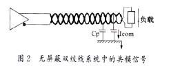
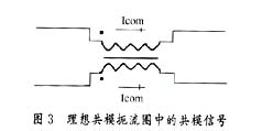
4 Selection of the magnetic module Each pair of wires in the twisted pair are wound with each other in a double spiral structure. As shown in Figure 2, the common-mode current Icom flows in the same direction on the two wires and returns to ground through the parasitic capacitance Cp. In this case, the currents produce magnetic fields of equal magnitude and polarity, and their outputs cannot cancel each other, causing radio frequency interference. In severe cases, the circuit board may be paralyzed. Therefore, designers must take measures to prevent: in addition to ensuring reasonable wiring, the selection of effective filter components is also an important aspect. The common mode choke part of the magnetic module can effectively reduce the radio frequency interference caused by the common mode signal. As shown in Figure 3: common-mode current flows through each side of the common-mode choke coil in the same direction, and an added magnetic field of equal magnitude and phase is established so that the common-mode choke coil exhibits high impedance to the common-mode signal. The common mode current of the mode choke is greatly reduced. The main parameters of the magnetic module are: leakage inductance, capacitance between lines and return loss. In general, the smaller the leakage inductance and the capacitance between the lines, the better the performance, and the return loss should comply with the ANSIX 3.263 TP-PMD regulations, as shown in Figure 4.


5 Conclusion The selection of important components such as OEMC, integrated optical transceiver module, RJ45, and magnetic module is related to the entire process of R & D, debugging and production of optical transceivers, which determines the development, performance and cost of products. It can be said that choosing the right component can not only benefit from each component, but also benefit from their combination. Designers must choose components to improve product performance and ensure product quality as the starting point.
2 Wang Tianxi, Li Hongru. Fundamentals of electronic technology. Beijing: Tsinghua University Press, 2000
3 Hubei Electromagnetic Compatibility Society. Principles and applications of electromagnetic compatibility. Beijing: National Defense Industry Press, 1996
4 TERRY OGLETREE. Upgrading and Repairing Net-works (2nd ed). Publishing House of Electronics Industry, 2001
5 ANDREW S. TANENBAUM. ComputerNetworks (3rded). PrenTIce-HallInternaTIonal, Inc. (3rd ed), 1997, 02
6 ALLAYER Communications. Fast Ethernet Fiber to TP Media Converter., 2000,11
7 NationalSemiconductor Corporation. DP83843BVJE PHYTER. . com, 2000, 09
8 Microlinear Corporation. DS6651-01. . com, 2001, 02
H05RN-F and H03RN-F are both types of flexible rubber cables commonly used for low voltage applications.
H05RN-F is a harmonized cable that is suitable for various indoor and outdoor applications. It is typically used for light to medium duty applications such as connecting portable electrical equipment, power tools, and appliances. The "H05" in the name refers to the harmonized code for rubber insulated cables with a rated voltage of 300/500V.
H03RN-F is also a harmonized cable, but it is designed for lighter duty applications compared to H05RN-F. It is commonly used for connecting small electrical devices and appliances, as well as for temporary installations. The "H03" in the name refers to the harmonized code for rubber insulated cables with a rated voltage of 300/300V.
Both H05RN-F and H03RN-F cables are known for their flexibility, durability, and resistance to moisture, oils, and mechanical stress. They are often used in construction sites, industrial environments, and outdoor events where a flexible and robust cable is required.
Flexible Copper Conductor Rubber Insulated Cable,Rubber Insulated Power Cable,Rubber Sheathed Power Cable,Electric Silicone Rubber Wire
Ruitian Cable CO.,LTD. , https://www.hbruitiancable.com