The various features of the high compression ratio standard provide a broad space for technicians to strike the best balance between complexity, latency, and other factors that constrain real-time performance.
Video compression with digital video coding can maintain acceptable video quality while minimizing video capacity. However, reduced video compression for ease of transmission and storage may sacrifice some image quality. In addition, video compression requires a high performance processor and a rich set of features in the design, as different types of video applications have different requirements in terms of resolution, bandwidth, and flexibility. The more flexible digital signal processor (DSP) not only meets these needs, but also leverages the rich options offered by advanced video compression standards to help system developers optimize their products.
The inherent structure and complexity of the video codec (codec) algorithm motivates us to adopt an optimization scheme. Encoders are very important because they must not only meet the application requirements, but they are also a major part of the video application's extensive processing tasks. Although the encoder is based on information theory, it still needs to be trade-off between different factors in the implementation process, so it is very complicated. Encoders should be highly configurable and provide developers with an easy-to-use system interface and optimized performance for a wide range of video applications.
Video compression features
The transmission or storage of raw digital video requires a lot of space. Advanced video codecs like H.264/MPEG-4 AVC can achieve compression ratios of up to 60:1 to 100:1 and ensure consistent throughput, which allows us to transmit with narrower transmission channels. And can reduce the space occupied by video storage.
Like the JPEG standard in the static image field, ITU and MPEG video coding algorithms also need to combine macroblocks in frames with techniques such as discrete transform coding (DCT or similar), quantization, and variable length coding. Once the algorithm establishes a baseline encoding (I frame), a large number of subsequent prediction frames (P frames) can be created by simply encoding the difference in visual content or residual values ​​between them. We can achieve this interframe difference using so-called motion compensation techniques. The algorithm first estimates the position of the previous reference frame macroblock into the current frame, then eliminates the redundancy and compresses the remainder.
Figure 1 shows the block diagram of a general motion compensated video encoder. The motion vector (MV) data describes the moving position of each block, which is created during the estimation phase, which is usually the most computationally intensive phase of the algorithm.
] 
Figure 1: Block diagram of a general motion compensated video encoder.
Figure 2 shows the P frame (right) and its reference frame (left). Below the P frame, the remaining portion (black portion) shows the amount of code remaining after the motion vector (blue portion) is calculated.

Figure 2: shows the P frame and reference frame of the remaining code after calculating the motion vector.
The video compression standard only specifies the bitstream syntax and decoding process, giving the encoder a lot of room for innovation. Rate control is also an area of ​​innovation that allows the encoder to assign quantization parameters to determine the noise in the video signal in an appropriate manner. In addition, the advanced H.264/MPEG-4 AVC standard provides macroblock size, quarter-pel resoluTIon, multi-reference frames, bi-directional frame prediction (B-frame), and adaptive ring. A variety of options, such as in-loop deblocking, increase flexibility and enhance functionality.
Diverse application requirements
Video application requirements vary widely. The various features of the Advanced Compression Standard provide a broad space for technicians to strike the best balance between complexity, latency, and other factors that constrain real-time performance. For example, we can imagine that video telephony, video conferencing, and digital video cameras (DVRs) have different requirements for video.
Video call and video conference
For video telephony and video conferencing applications, transmission bandwidth is often the most important issue. Depending on the link, the bandwidth can range from tens to thousands of kilobytes per second. In some cases, we can ensure the speed of transmission, but for the Internet and many corporate intranets, the transmission speed will vary greatly. Therefore, video conferencing encoders typically need to meet different types of links and should adapt to changing available bandwidth in real time. After the transmitting system receives the conditions of the receiving end, it should constantly adjust the coded output to ensure the best video quality with the least possible video interruption. If the conditions are poor, the encoder can respond by reducing the average bit rate, skipping frames, or changing the image group (GoP, which is a mixture of I and P frames). I frames are compressed less than P frames, so the overall bandwidth required for GoP with fewer I frames is lower. Since the visual content of a video conference usually does not change, the number of I frames used can be reduced, making it lower than the level of entertainment applications.
H.264 uses an adaptive in-loop deblocking filter to process the edges of the block to keep the video smooth between the current frame and subsequent frames, thereby improving video encoding quality, which is especially effective at low bit rates. In addition, turning off the filter also increases the amount of visual data at a given bit rate and increases the motion estimation resolution from one-quarter pixel accuracy to one-half or more. In some cases, we may need to reduce the quality of deblocking filtering or reduce the resolution, thus reducing the complexity of the encoding work.
Since the provisioning of packets over the Internet does not guarantee quality, video conferencing often benefits from an encoding mechanism that increases fault tolerance. As shown in Figure 3, the progressive strip of the P frame can be used for intra coding (I picture strip), so that the complete I frame is no longer needed after the initial frame, and the entire I frame can be reduced. And the problem of image breakage.

Figure 3: Continuous strip images of P frames can be used for intra coding.
Digital video
Digital video cameras (DVRs) for home entertainment are probably the most widely used real-time video encoder applications. For such a system, how to achieve the best balance between storage capacity and image quality is a big problem. Unlike video conferencing, which cannot tolerate delays, compression of video recording can withstand some real-time delay if the system buffers enough memory available. A design that meets the actual requirements means that the output buffer can handle several frames, which is enough to keep the disk stable and continuous. However, in some cases, because the visual information changes very quickly, causing the algorithm to generate a large amount of P-frame data, the buffer may be blocked. As long as the blocking problem is solved, the image quality can be improved again.
One of the mechanisms for effectively making trade-offs is to instantly change the quantization parameter Qp. Quantization is one of the steps in the final phase of the compressed data algorithm. Increasing the quantization reduces the bitrate output of the algorithm, but the image distortion increases in proportion to the square of Qp. Increasing Qp will reduce the bitrate output of the algorithm, but it will also affect the quality. However, since this change occurs in real time, it helps to reduce frame skipping or picture breakage. If the visual content changes very quickly, such as when the buffer is congested, then although the image quality is reduced, it does not attract attention as the content changes slowly. After the visual content returns a lower bit rate and the buffer is emptied, Qp can be reset to normal.
Encoder flexibility
Because developers can use DSPs in a variety of video applications, DSP encoders should be designed to take advantage of their flexibility in compression standards. For example, encoders based on Texas Instruments' mobile application area OMAP media processor, TMS320C64x+DSP or DaVinciTM processor are highly flexible. To maximize compression performance, each encoder can be used to take full advantage of its platform's DSP architecture, including the Video and Image Co-Processor (VICP) built into some processors.
All encoders use a basic set of APIs with default parameters, so the system interface does not change regardless of the type of system used. Extended API parameters allow the encoder to meet the requirements of a particular application. By default, parameters can be preset to high quality, and high-speed preset settings are also available. The program uses extended parameters to override all preset parameters.
Extended parameters enable applications to meet H.264 or MPEG-4 requirements. The encoder can support several options, such as YUV 4:2:2 and YUV 4:2:0 input format, motion compensation for minimum quarter-pixel resolution, various I-frame intervals (from I frame to I frame) There are no subsequent I frames after the first I frame), Qp bit rate control, access motion vectors, deblocking filter control, simultaneous encoding of two or more channels, and I-strips and the like. The encoder can dynamically and unrestrictedly determine the search range of the default motion vector, a technique that is an improvement over fixed range search.
In addition, there is usually a sweet spot, which is the optimal output bit rate for a given input resolution and frames per second (fps). Developers should be aware of this optimal point of the encoder to achieve the best design balance between system transfer and image quality in the design.
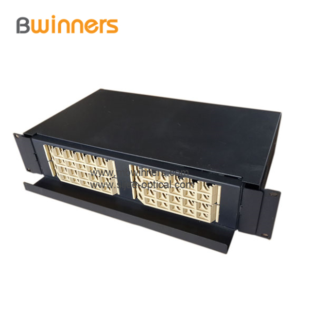
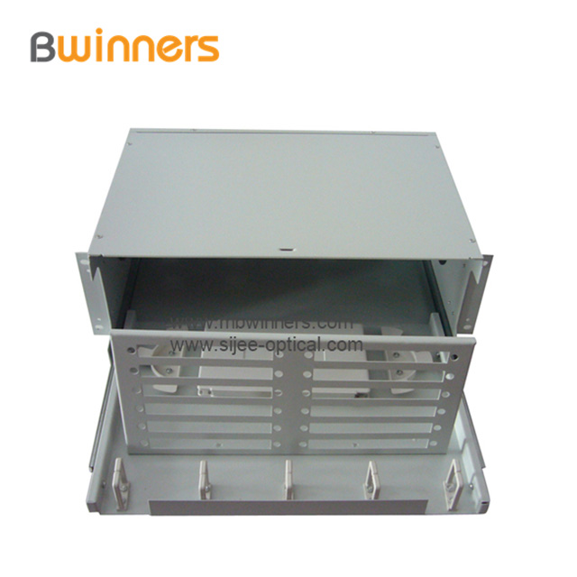
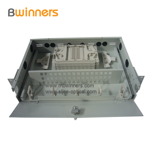
Fiber Optic Patch Panel, Termination Box Fiber Optic Termination Box/Patch Panel(OTB)designed according to the standard 19-inch cabinet, it is made of cold rolled steel of high grade and welded in its entirety with goods appearance, cabel can enter from the left or right side .
Fiber Optic Termination Box/Patch Panel(OTB) perform fiber splicing, distribution, termination, patching, storage and management in one unit. They support both cross-connect and interconnect architecture, and provide interfaces between outside plant cables and transmission equipment.


Fiber Optic Patch Panel,Fiber Optic Distribution Panel,Fiber Optical Patch Panel
Ningbo Bwinners Optical Tech Co., Ltd , https://www.sijee-optical.com