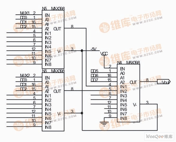
MUX circuit
The MUX circuit is shown in the figure. The main function is to select 35 tested voltages to ensure that only one voltage enters the subsequent analog-to-digital conversion circuit for data conversion at a certain time. The MUX circuit consists of two stages. The front stage consists of five eight-to-one multiplexers. The 35 measured voltages are conditioned and connected to these MUXs. Only two wiring diagrams are shown in the figure. The three blocks are basically the same, and the latter stage consists of a multiplexer that further selects the five voltages of the front stage output. In the figure, signals MUX1 and MUX2 select the pre-stage chip, signals DD0, DD1, and DD2 select the channels of the previous stage, and signals DD5, DD6, and DD7 select the channels of the subsequent stage. These signals are generated by the CPLD.
57 Jack.China RJ11 Jack 1X5P,RJ11 Connector with Panel supplier & manufacturer, offer low price, high quality 4 Ports RJ11 Female Connector,RJ11 Jack 6P6C Right Angle, etc.
The RJ-45 interface can be used to connect the RJ-45 connector. It is suitable for the network constructed by twisted pair. This port is the most common port, which is generally provided by Ethernet hub. The number of hubs we usually talk about is the number of RJ-45 ports. The RJ-45 port of the hub can be directly connected to terminal devices such as computers and network printers, and can also be connected with other hub equipment and routers such as switches and hubs.
RJ11 Jack 1X5P,RJ11 Connector with Panel,4 Ports RJ11 Female Connector,RJ11 Jack 6P6C Right Angle
ShenZhen Antenk Electronics Co,Ltd , https://www.antenkwire.com