Ringing effect is one of the many factors that affect the quality of the restored image. It is caused by the improper image model selected in image restoration. The direct cause of the ringing effect is the loss of information during image degradation. In particular, the loss of high-frequency information severely degrades the quality of the restored image and makes it difficult to perform subsequent processing on the restored image.
The ringing effect is caused by selecting an inappropriate image model in the image restoration. Incorrect selection of the point spread function in the image restoration is also another cause of the ringing effect in the restoration result, especially the selected point diffusion. When the size of the function is larger than the size of the real point spread function, the ringing phenomenon is more obvious; the direct cause of the ringing effect is the loss of information in the process of image degradation, especially the loss of high frequency information.
The effect of ringing on the quality of restored images is serious. Many scholars have conducted extensive studies on the method of suppressing ringing. However, most image restoration methods have disadvantages at this point, causing the ringing effect during recovery to be almost impossible. Avoid, especially in the presence of noise, it will confuse the high-frequency characteristics of the image, making the ringing effect more pronounced.
The multiplication in the frequency domain is equal to the convolution of the spatial domain function. Low-pass filtering of the image is the product of the low-pass filtering function in the frequency domain and the original function, that is, the convolution of the low-pass filtering function in the spatial domain with the original function. The ideal low-pass general form h(x) is obtained from its transfer function by inverse Fourier transform. The curve resembles a cosine function, the amplitude is getting smaller, the curve of the pixel point is approximated by the pulse function f(x), and the convolution Actually, the pulse function h(x) is copied to the position corresponding to f(x). Obviously, the original clear point of h(x) is blurred. For a complex image, ringing occurs.
Reduction and suppression of ringing method in practical circuits(1) Series resistance. By using a transmission line with a large resistance or artificially connecting an appropriate damping resistor, the amplitude of the pulse can be reduced, thereby achieving the purpose of reducing the degree of overshoot and ringing. However, when the value of the input resistance is too large, the pulse amplitude cannot be reduced excessively, and the leading edge of the pulse is delayed. Therefore, the value of the series damping resistance should be appropriate, and a non-inductive resistor should be used. The connection value of the resistor should be close to the receiving end.
(2) Reduce lead inductance. Trying to reduce the lead inductance of the line and the transmission line is the most basic method. The general principle is: shorten the length of the lead as much as possible; add the vinegar to the line and the width of the printed copper foil; reduce the signal transmission distance, use the small lead inductor inductance Devices and so on, especially when transmitting very steep pulse signals, should pay attention to these issues.
(3) Because the equivalent inductance and equivalent capacitance of the load circuit can also affect the transmitting end, so that the pulse waveform generates overshoot and ringing, therefore, the equivalent inductance and capacitance of the load circuit should be reduced as much as possible. Especially when the ground wire of the load circuit is too long, the formed ground inductance and stray capacitance are considerable, and its influence cannot be ignored.
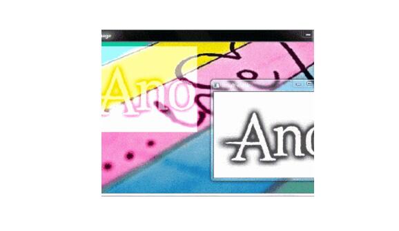
In image processing, an image is filtered. If the selected frequency domain filter has a steep change, the filtered image will produce “ringingâ€. The so-called “ringing†means the sharp change of the gray level of the output image. The turbulence at the place is as if the air created by the bell was struck. As shown below:
The following two enhancements can be linked by the convolution theorem:
Frequency domain enhancement: 
Spatial convolution: 
Where f, g, h are the input image, the enhancement image, and the spatial filter function; F, G, and H are their respective Fourier transforms. * is a convolution symbol.
The key to understanding low-pass filtering as a convolution process in the spatial domain is the characteristics of h(x,y): h(x,y) can be divided into two parts: the central part at the origin, and the cycle around the center The outer part of the distribution. The former decided to be ambiguous and the latter decided to ring. If the outer part has obvious oscillation, g(x,y) will ring. Using the Fourier transform, we find that if the filter function in the frequency domain has steep changes, the spatial filter function obtained by the inverse Fourier transform will oscillate at the periphery.
Three commonly used low-pass filters are given below: Ideal, Butterworth, and Gaussian. And analyze the characteristics of their use of the spatial filter function to verify the above conclusions.
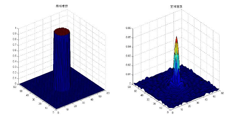
Ideal type: 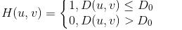
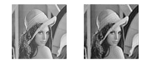
The ideal filter will appear ringing. It can be seen that there is a sharp oscillation around the image of the spatial filter function.
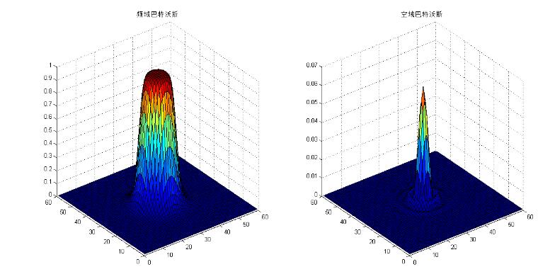
Butterworth type: 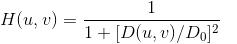
For the order, Butterworth of the first order does not have "ringing". As the order increases, the ringing phenomenon becomes more obvious. Taking n=2 in the figure below, we can see that the outer part of the airspace function has oscillated.
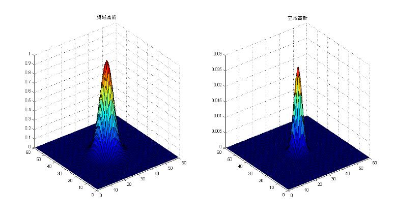
Gaussian type: 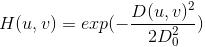
The Fourier transform of the Gaussian function is still a Gaussian function, so the Gaussian filter does not produce "ringing."
The above image creation program:
[objc] view plain copyclose all;
Clear all;
D0=8;
M=60; N=60;
C1=floor(M/2);
C2=floor(N/2);
H1=zeros(M,N); %ideal
H2=zeros(M,N); % Butterworth type
H3=zeros(M,N); % Gaussian
Sigma=4;
n=4;% Butterworth order
For i=1:M
For j=1:N
d=sqrt((i-c1)^2+(j-c2)^2);
If d"=d0
H1(i,j)=1;
Else
H1(i,j)=0;
End
H2(i,j)=1/(1+(d/d0)^(2*n));
H3(i,j)=exp(-d^2/(2*sigma^2));
End
End
Draw2(h1, 'ideal');
Draw2(h2, 'Batworth');
Draw2(h3,'Gauss');
Function draw2(h,name)
Figure;
Surf(h);title(strcat('frequency domain',name));
Fx=abs(ifft2(h));
Fx=fftshift(fx);
Figure;surf(fx);title(strcat('Airspace',name));
Stainless Steel Screw,Stainless Steel Grub Screws,Stainless Steel Open Eye Hook Screw,Stainless Steel Drywalll Screw
ShenZhen Haofa Metal Precision Parts Technology Co., Ltd. , https://www.haofametal.com