In order to prevent the control signal line between the plc and the inverter from being disturbed by the space electromagnetic field, the shield wire can be connected to the outer layer of these control signal lines to improve the anti-interference ability of the system. It must be noted that this type of wiring can only be selected for the grounding point of the shield. Whether it is on the side of the PLC or on the side of the inverter. Generally selected at the signal receiving end, that is, the side of the inverter. In this way, the anti-interference ability of the system can be improved. If the shielded wire is grounded at both ends, current will flow through the shielded wire, which will not only improve the system's anti-interference ability, but will increase the external interference to the PLC.

1. The shielded wire should be as far as possible to the end of the low potential. It can be understood that we generally think that the ground potential is “0â€. In the fact, if there are two grounding ends, there will be a potential difference between the two grounding ends at a certain moment. There will be current flow between the two wires, which is also an interference.
2. In practical applications, if the place where the control cable passes is complicated and requires multi-terminal grounding, we generally take the shield layer and ground it in different places. This method is often used in the grounding of the communication cable of the control equipment communication line of the factory.
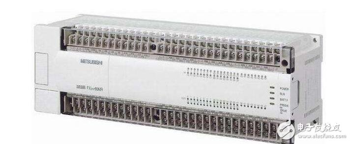
That is, which input signals are used, what control method is used; which outputs are external to the plc, and what components are used to perform the driving load. and many more.
2, the preliminary design of the control systemControl system design is a gradual process. Determine a preliminary control plan and solve the main control part. For other less important ones, you can not consider it.
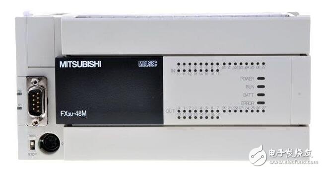
Select the appropriate control element according to the input and output, calculate the required number of input and output points, and select the appropriate plc model. Plc wiring diagram is drawn according to the plc machine and the input and output control components.
4, according to the control requirements and input and output wiring diagram to draw ladder diagramThe key step is now programmed on the computer through software. In addition to mastering the various commands of the plc, the ladder diagram design must understand the basic working principle and hardware structure of the plc. Software search and help functions can be used to find the block of instructions you need faster during programming.
5, improve the above design contentImprove and simplify the ladder diagram, you can further modify and improve the wiring diagram and the main circuit or even the preliminary design, add monitoring, alarm, display, protection and other functional measures to achieve a unified improvement.
6, simulation and debuggingAfter simulating the programmed ladder diagram, make sure that there is no problem with the ladder diagram before debugging online. The emulation software does not support certain instructions. This part can only be used for analog debugging or on-site debugging on plc.
7, installation equipment debuggingThe ladder diagram is downloaded to the plc, and the control components are installed and wired according to the circuit diagram, and the test operation is performed on the electrical control device.
Plc combination circuit design programming methodThe control circuit can be divided into a combination circuit and a sequential circuit according to a logical relationship, and these two circuits may be included in a complicated control circuit.
Combination circuit designThe circuit whose control result is only related to the input is called a combination circuit. Since the control result of the combination circuit is only related to the state of the input variable, it can be calculated by using logic algebra.
The ladder circuit design steps of the combined circuit are generally as follows:
(1) List the truth table according to the control conditions. (2) Write the logical expression from the truth table and simplify it. (3) Draw a ladder diagram based on a logical expression.For example, a common dual-control switch in the staircase corridor is controlled by plc, and the plc control wiring diagram and ladder diagram are designed.
a. Draw the plc wiring as shown.
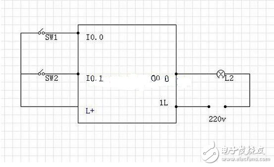
Plc wiring diagram
b. According to the title, it is known that the two switches have four states. When only one of the switches is active, the light is on. When both switches are in motion or not operating, the light does not illuminate, and a truth table is drawn.
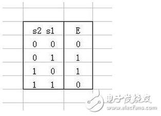
Truth table
Write a logical expression from the truth table
E=s2 non-s1+s2s1 non
c. Draw a ladder diagram based on the logical expression.
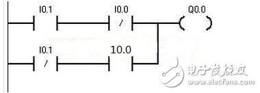
Ladder diagram
Power 90W ,output voltage 15-24V, output current Max 6A, 10 dc tips.
We can meet your specific requirement of the products, like label design. The plug type is US/UK/AU/EU. The material of this product is PC+ABS. All condition of our product is 100% brand new. OEM and ODM are available in our company, and you deserve the best service. You can send more details of this product, so that we can offer best service to you!
90W Desktop Adapter,90W Desktop Power Supply,90W Desktop Power Cord , 90W Desktop Power Adapter
Shenzhen Waweis Technology Co., Ltd. , https://www.waweisasdapter.com