Abstract : Using Texas Instruments DLP technology, a new generation of high-efficiency full-color large-field automotive head-up display (HUD) systems with augmented reality capabilities can be realized. The uniqueness of DLP technology enables it to address common design issues in head-up display systems, including managing extreme environments and thermal loads, delivering high brightness and high resolution, and enabling dynamic dimming. In addition, the DLP projection-based architecture provides a flexible optical design that creates a virtual large-field display that expands the driver's field of view and provides assistance to the driver. This article briefly describes how DLP solid-state lighting operations and DLP technology solve the above-mentioned common HUD design challenges. DLP technology can be used to create advanced solutions for future automotive head-up display applications.
introduction
Texas Instruments DLP projection technology is a widely used and proven technology for a variety of display applications, including: handheld projectors, conference rooms, and digital cinema. DLP technology meets the needs of advanced HUD systems. The DLP electronic system supports video processing and formatting to meet the needs of future HUD systems that require graphics and video images. The concept of a high dynamic range LED control system has been proven to provide conditions for viewing in daylight and night. In addition, with the implementation of optical design based on DLP technology, relevant personnel can more flexibly solve the optical design challenges, shape specification limitations and thermal load management issues of future automotive HUD systems.
DLP electronic system overview
The concept of the DLP car head-up display system consists of two subsystems, a video processing and formatting subsystem that utilizes the DLP controller chip, and an LED control system that utilizes Piccolo microcontrollers (MCUs). Figure 1 shows a typical DLP heads up display system application.
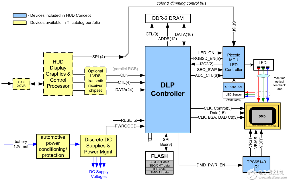
Figure 1. Typical DLP heads up display system application
The DLP HUD controller is responsible for receiving and processing the video and commands received from the external display graphics processor. It is capable of receiving 24-bit parallel video data at frame rates up to 60 Hz. The received video data is processed by programmable image scaling, grayscale, sub-image support, and frame adjustment factors, and finally output to the DMD for final graphic display. In addition, the DLP HUD controller provides strobe signals that activate red, green, and blue LEDs to keep pace with the data being displayed on the DMD device for high-brightness, highly saturated colors and high-contrast graphics with extremely fast display rates. .
The Piccolo MCU-based LED control system is responsible for precisely controlling the color and brightness over the entire operating temperature range and the aging range of the red, green and blue LEDs. In addition, it supports natural dimming with high dynamic brightness for day and night driving in HUD applications.
The LED control system uses a luminous flux feedback scheme based on the PWM hysteresis control method. In continuous mode (CM), the entire output LED enable pulse period is turned on in near direct current (DC) mode to maintain a constant illumination level. In discontinuous mode (DM), each pulse amplitude is controlled by the same hysteresis control loop, but only the triggered pulse source can be enabled. The DLP controller measures the specific number of pulses per LED. Intermittent mode allows for very low output flux levels while maintaining control accuracy.
An increase in LED temperature and LED aging will result in higher current levels being used to produce the desired level of light flux. When the maximum LED current is reached before the luminous flux control loop reaches the desired luminous flux level, the Piccolo MCU will perceive this condition and proportionally reduce all three LED flux levels until all LEDs return to luminous flux. Under feedback control. In this way, the system provides the best picture for the entire life of the LED and achieves the ultimate brightness level.
The LED control system receives the brightness/dimming control commands from the upstream control source via the SPI bus input. Piccolo analyzes commands from the LED control system, such as RGB LED amplitude levels, continuous or discontinuous mode, and configures the DLP controller via a dedicated I2C bus.
The DLP electronics system is based on automotive-grade components that enable all the functions required for the operation of the HUD system. The electronic system includes a video processing and LED control system that supports a high dynamic dimming range for day and night driving situations.
High dynamic range LED control system concept
HUD applications require very high dynamic range, supporting more than 15,000 cd/m^2 during daytime operation, and in nighttime environments where the light is very dark, the brightness of the display graphic cannot be less than 3 cd/m^2. The HUD system must be able to maintain a full-color depth at the target white point with a dynamic range of over 5000:1. The LED driver control system was developed specifically for automotive HUD applications and has demonstrated a full range of features.
The Piccolo MCU's LED driver control system manages red, green and blue LED amplitude modulation, maintains normal white points, and synchronizes LED illumination with DLP controllers. The DLP controller provides high speed data for the DMD and associated RGB LED enable signals. Each device selected for the LED driver control circuit can be used with Texas Instruments Q1 (designed for automotive) components that meet automotive standards.
The DLP projection system uses pulse width modulation (PWM) red, green and blue light to create a full color depth pattern that integrates and synchronizes the dimming function within the standard PWM technology used.
The system uses optical hysteresis feedback based on LED light output. In order to achieve higher brightness, the continuous feedback mode is used to maintain the amplitude of the steady state during the period within the bit segment. This example is shown in Figure 2. Continuous mode feedback has proven to work in the 100:1 dimming range.
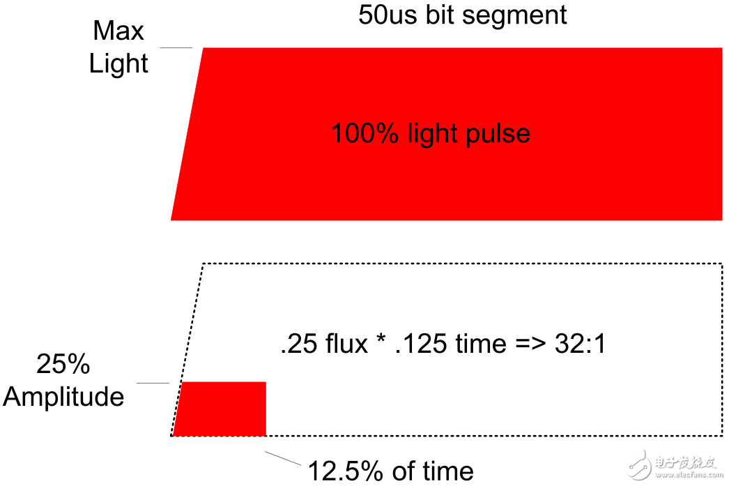
Figure 2. Continuous dimming mode
The system also uses intermittent mode feedback to generate a small amount of pulsed light. This technology extends the dynamic range to a ratio of over 5000:1. Figure 3 shows an example of a discontinuous mode light pulse.
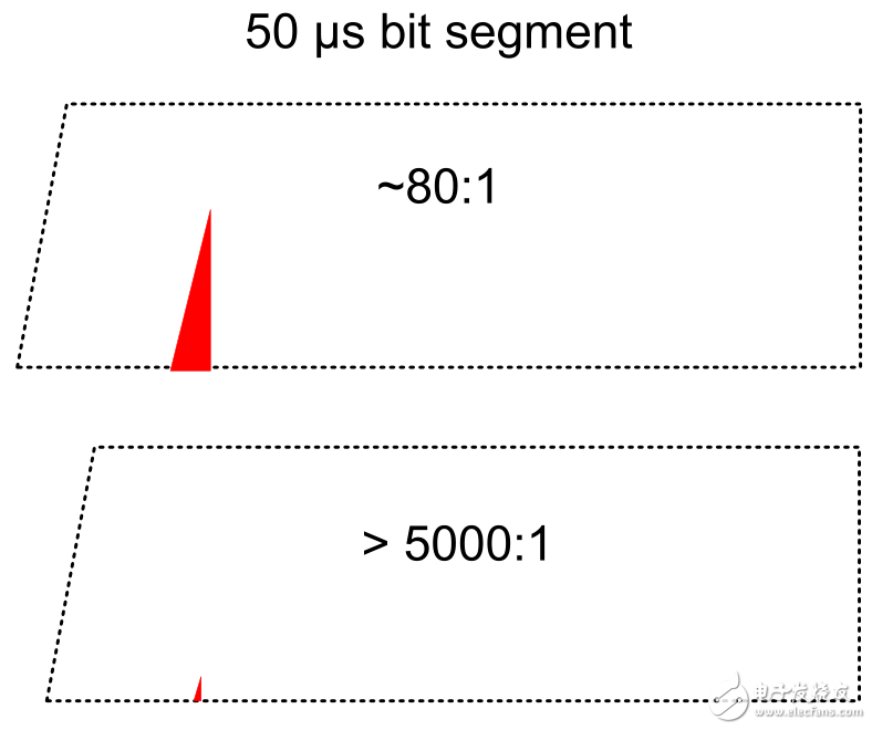
Figure 3. Intermittent dimming mode
The LED control system can be used in continuous and intermittent operation modes, exhibiting natural dimming from 15,000 cd/m^2 to less than 3 cd/m^2. The measured data in the Texas Instruments concept system is shown in Figure 4.
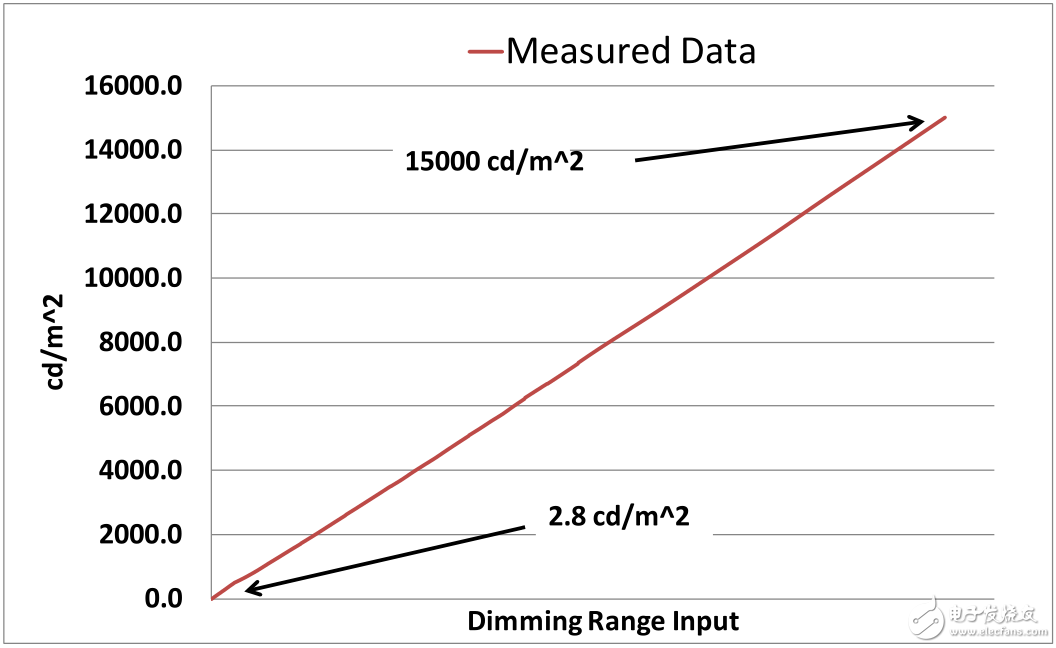
Figure 4. Measured white light from the Texas Instruments Concept System
In addition to achieving a large dynamic range, white spots must be maintained. In order to implement in the Texas Instruments concept system, we chose D65 as the target white point, and D65 is the standard adopted by most HDTVs. The target chromaticity value of this white point is x=0.313 and y=0.329. As shown in Figures 5 and 6, the measured data in the dynamic range remains close to the target white point, and the total deviation from the target chromaticity point is not less than +/- 0.01.
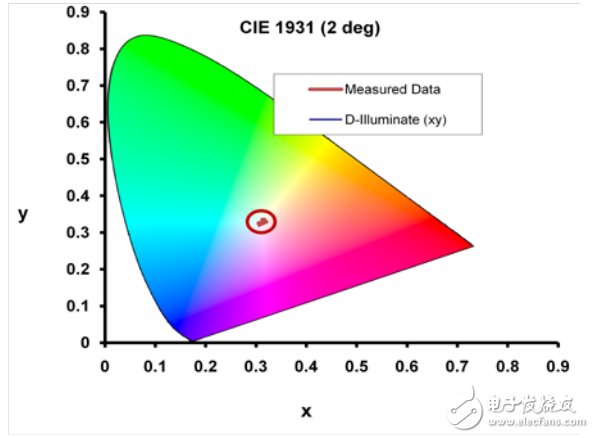
Figure 5. The measured white point of the Texas Instruments concept system
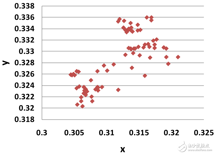
Figure 6. Measured white points outside the dynamic range
In summary, the implemented LED driver control system is based on automotive-grade components that demonstrate high dynamic range for day and night viewing conditions while maintaining accurate white point control.
Mtu Generator Set,Diesel Power Generator,Diesel Engine Generator,Silent Diesel Generator
Yangzhou Hengyuan Electromechanical Equipment Co., Ltd. , https://www.lchypower.com