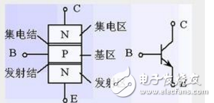
NPN is the current (IC) of C→E controlled by the current (IB) of B→E. The E potential is the lowest, and the C potential is the highest when normal amplification, ie VC > VB > VE
PNP is the current (IC) of E→C controlled by the current (IB) of E→B. The E potential is the highest, and the C potential is the lowest when normal amplification, ie VC < VB < VE
In short, VB is generally in the middle, VC and VE are on both sides, which is consistent with the position in the usual BJT symbol, you can use this to help your image thinking and memory. Moreover, although the poles of the BJT are not pure resistors, the voltage direction and the current direction are also the same, and there is no case where the current is high from the low potential.
Today's popular circuit drawing method is usually used to "male men and women", oh no, "yang under the shade", that is, "the positive power supply is under the negative power supply." In the NPN circuit, E is eventually connected to the floor (direct or indirect), and C is ultimately connected to the ceiling (direct or indirect). The PNP circuit, on the other hand, is ultimately connected to the floor (directly or indirectly), and E is ultimately connected to the ceiling (directly or indirectly). This is also to satisfy the relationship between VC and VE above. In the general circuit, with NPN, you can get the version of PNP according to the "up and down symmetric exchange" method. At any time, as long as the above six "polar" relationships (4 current directions and 2 voltage inequalities) are met, the BJT circuit may work properly. Of course, to ensure normal operation, it must also be ensured that these voltages and currents meet some further quantitative conditions, the so-called "working point" conditions.
For the NPN circuit:
For the collinear configuration, it can be roughly understood as VE as a "fixed" reference point, by controlling VB to control VBE (VBE = VB-VE), thereby controlling IB, and further controlling the IC (from a higher potential) Into the C pole, you can also think of the C pole as the funnel of the upward water.)
For the common base configuration, it can be understood that VB is regarded as a fixed reference point, and VBE (VBE=VB-VE) is controlled by controlling VE, thereby controlling IB and further controlling the IC.
If the desired output signal is not in the form of current, but in the form of voltage, then a resistor RC is applied to the C pole to turn the IC into a voltage IC*RC. However, in order to satisfy VC>VE, the other end of the RC is not grounded, and the positive power supply is connected.
And purely from the perspective of BJT itself, regardless of where the input signal comes from, the common-shot configuration and the common-base configuration are very similar, anyway, they control VBE, but only a "fixed" VE, change VB, a fixed VB, Change VE.
For the common-emitter configuration, there is no “fixed reference pointâ€, which can be understood as the use of VBE with small changes in IC or IE, so that regardless of how the output current IE changes (of course, there is a limit), VE basically follows the VB change. (VE=VB-VBE), VB rises, VE also rises, VB decreases, and VE also decreases, which is the origin of the name of the voltage follower.
The PNP circuit is symmetrical to the NPN, for example:
For the collocation configuration, it can be roughly understood as VE as a "fixed" reference point, control VB to control VEB (VEB = VE-VB), thereby controlling IB, and further controlling the IC (from C pole to lower potential) Where you can, you can also think of the C pole as the downward discharge pipe).
For the common base configuration, it can be understood that VB is regarded as a fixed reference point, and VEB (VEB=VE-VB) is controlled by controlling VE, thereby controlling IB and further controlling the IC.
......
All of the above VE's "fixed" words are quoted. Since the E point is sometimes the introduction point of the series negative feedback, the VE also changes, but this change is the result of the feedback signal, that is, the cause of the change by VB. 
Silicone Protective Sleeve,Silicone Sleeve For Glass Bottle,Silicone Water Bottle Sleeve,Bottle Silicone Sleeve
Nantong Boxin Electronic Technology Co., Ltd. , https://www.ntbosen.com