With the continuous development of science and technology, laser ranging, microwave radar ranging, ultrasonic ranging and infrared ranging have appeared in the field of ranging. As a measurement method with wide application and high measurement accuracy, infrared ranging uses the characteristics of non-diffusion and small refractive index when transmitting infrared rays, and is used according to the time required for infrared rays to be emitted from the transmitting module to be reflected by the object and accepted by the receiving module. The corresponding ranging formula is used to measure the distance of the object.
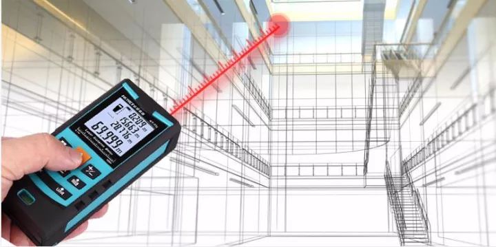
Infrared ranging was first introduced in the 1960s and is a measurement method using infrared rays as a transmission medium. The research of infrared ranging has an unusual significance. It has other characteristics that are not available in other ranging methods. The technical difficulty is relatively small. The system has low cost, good performance, convenient and simple use, and it is not suitable for all walks of life. The lack of contribution, so its market demand is greater, and the development space is wider. Infrared range finder is a precise distance measurement using modulated infrared light. The measurement range is generally 1-5 km.

Infrared ranging sensor has several features, long-distance measurement, can measure long distance without reflector and low reflectivity; synchronous input, multiple sensors can be measured synchronously; wide measurement range, response Short time; compact design, easy to install, easy to operate; so its application value is relatively high.
Common methods and principles of infrared ranging
Time difference method
The time difference method is to calculate the time difference t between the infrared transmitting end transmitting signal and the receiving end receiving signal of the infrared ranging sensor into the single chip microcomputer, and calculate the propagation distance L by the light propagation distance formula.

Where c is the propagation speed of light  .
.
Principle of distance measurement by reflection energy method
The reflection energy method is controlled by the emission control circuit to control the light-emitting element to emit a signal (usually infrared light) to the target object, and after being reflected by the object, it is transmitted back to the receiving end of the system, and the distance of the light energy received by the photoelectric converter is used to calculate the distance of the target object. L.

Where P is the energy received by the receiving end, K is a constant, the size is determined by the output power of the transmitting system, the conversion efficiency, and d is the diffuse reflectance of the measured object.
Phase method
The phase ranging method uses the frequency of the radio band to amplitude modulate the infrared laser beam and measure the phase delay generated by the modulated light to and from the round trip, and then converts the distance D represented by the phase delay according to the wavelength of the modulated light. The measurement accuracy is very high, and the relative error can be kept within one hundredth, but the target to be tested must be able to actively emit radio waves to generate corresponding phase values.

Where c is the propagation speed of light  ,
,  Is the angular frequency of the modulated signal.
Triangulation principle
Triangulation principle. The infrared emitter emits an infrared beam at a certain angle, and when it encounters an object, the beam is reflected back, as shown in FIG. After the reflected infrared light is detected by the CCD detector, an offset value L is obtained. Using the triangular relationship, after knowing the emission angle a, the offset distance L, the center moment X, and the focal length f of the filter, the sensor The distance D to the object can be calculated from the geometric relationship.
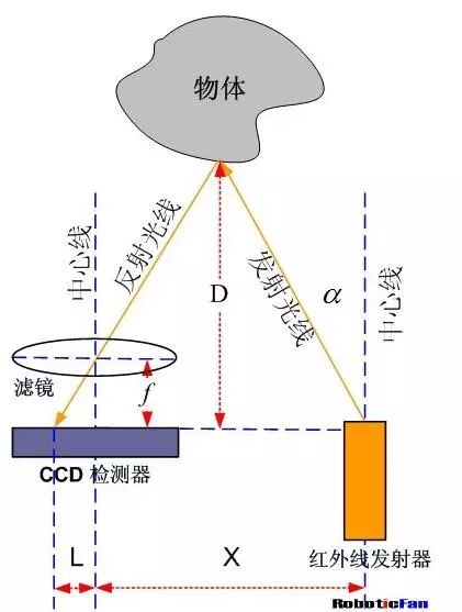
How the infrared ranging system works
The reflection energy method can be widely used in mass-produced opto-mechatronics products because of its simple structure, small size and low cost. The infrared ranging system based on such methods is mainly introduced later in this paper.
The basic principle of the reflected energy method is that the infrared light emitting diode of the infrared emitting circuit emits infrared light, and after being reflected by the obstacle, the photosensitive receiving tube of the infrared receiving circuit receives the reflected light of the front object, thereby judging whether there is an obstacle in front. According to the intensity of the emitted light, the distance of the object can be judged. Since the intensity of the light received by the receiving tube changes with the distance of the reflected object, the reflected light is strong when the distance is close, and the reflected light is weak when the distance is long.
Because infrared is an electromagnetic wave between visible light and microwave, it not only has the characteristics of visible light transmission, reflection, refraction, but also some characteristics of microwave, such as strong penetration ability and can penetrate some Opaque substances, etc. The infrared sensor includes an infrared emitting device and an infrared receiving device. All objects in nature emit infrared light as long as the temperature is above absolute zero. Therefore, infrared sensors must have stronger transmitting and receiving capabilities.
Basic structure and system of infrared ranging
Infrared ranging process
The working process of infrared ranging is simply aiming at the target, then turning on the power, starting the transmitting circuit, transmitting the infrared signal like the target through the transmitting system, and simultaneously sampling the transmitting signal as the pulse signal of the counter opening, starting the counter. The clock oscillator is like a counter input pulse. The infrared echo reflected by the target acts on the photodetector and transforms into an electrical pulse signal. It is amplified by the amplifier and enters the counter. As the counter closes the signal, the counter stops counting and the counter During the period from the opening of the door to the closing of the door, the number of clock pulses entered is calculated by the target distance. The distance measurement formula is:

Where: L——the distance to be measured;
C——the speed of light;
t - the time required for the light pulse to travel back and forth over the distance to be measured.
The target distance can be obtained by the above equation as long as the time required for the optical pulse to travel back and forth at the distance to be measured is obtained. The principle and structure of the infrared pulse are relatively simple, the distance measurement is long, and the power consumption is small.
Infrared ranging system block diagram
The system is mainly composed of five parts: infrared transmitting circuit, infrared receiving circuit, amplifying circuit, single chip circuit, and decoding display circuit. The working process is as follows:
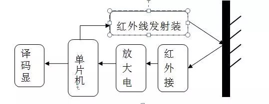
When the system works, a laser beam is emitted by the transmitting unit, and after reaching the object to be tested, it is diffused and reflected back. After receiving, amplifying and shaping, the receiving unit displays the distance of the target object after the calculation by the distance calculating unit.
Main components of infrared ranging system
Infrared emitting device
Infrared emitting device is the longest used infrared light emitting diode. It has the same structural principle and manufacturing process as ordinary light emitting diode. It is a semiconductor device with only one PN junction, but all materials are different, and the infrared light emitting diode is made of potassium arsenide. Aluminium arsenate, etc., the most widely used is potassium arsenide.
Infrared light-emitting diodes are generally packaged in epoxy, glass, plastic, etc., in addition to white transparent material packaging, they can also be seen encapsulated in blue transparent material. According to the size of the luminous power, the infrared light-emitting diode can be divided into three types: low power, medium power and high power. In addition, the infrared light emitting diode has a side light emitting type in addition to the top surface light emitting type. Small power tubes are generally packaged in a full plastic package, and some are ceramic bases. The top ends are packaged with glass or epoxy lenses. The medium and large power tubes are usually made of threaded metal bases for mounting heat sinks. As the luminous power is increased, the corresponding volume of the tube also increases.
Main parameters of infrared light-emitting diode
Forward operating current
Refers to the maximum average current allowed by the infrared light-emitting diode when it is working for a long time. Because the current passes through the PN junction, it consumes a certain amount of power and causes the tube to heat up. If the tube runs longer than I, it will burn out due to overheating. Therefore, the maximum used. The average forward operating current must not exceed I.
Optical power
Refers to the portion of the electrical power input to the LED that is converted to the optical output power. The greater the optical power, the farther the transmission distance is.

Refers to the wavelength of the light corresponding to the maximum intensity of the near-infrared light emitted by the infrared light-emitting diode. When the infrared receiving tube is selected, the peak wavelength of the received light should be as close as possible.  .
.

Refers to the magnitude of the reverse current when the tube is not reversely broken. It is desirable that the smaller the better.

Due to the presence of the PN junction capacitance of the infrared light-emitting diode, its operating frequency is affected. Now, the corresponding time of the infrared LED is generally  The maximum operating frequency is tens of megahertz.
Infrared photodiode
We know that semiconductors have a photoelectric effect, that is, the use of a light semiconductor can change the resistivity of a semiconductor. Photodiodes can be fabricated using the photoelectric effect of semiconductors, and different semiconductor materials respond differently to incident light of different wavelengths.
The photodiode has two forms of top surface receiving and side receiving light. It is also packaged in plastic, glass, epoxy and other materials.
Main parameters of photodiode
Photocurrent IL
Refers to the current flowing through the tube when the incident light intensity is a certain value under a certain reverse voltage. The photocurrent of a photodiode is typically tens of μA and is proportional to the incident light intensity.
Dark current ID
Refers to the current flowing through the tube in the absence of light at a certain reverse voltage. Generally, under 50V back pressure, the ID is less than 0.1μA.
Reverse working voltage UR
It refers to the highest reverse operating voltage allowed when the photodiode reverse current is less than 0.2μA-0.3μA in the absence of illumination, generally around 10V, up to tens of volts.
Infrared ranging hardware circuit
MCU minimum system
The microcontroller consists of a CPU, on-chip memory, timer system, serial port, A/D, parallel I/O port, interrupt and reset system. Figure:
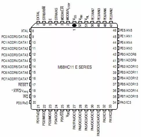
Control board ASBUS bus
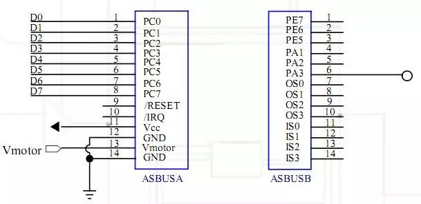
Simple like ISA and PCI bus. The stacked ASBUS expansion card makes it easy to extend the functionality of the control board. A bus usually contains dozens of discrete lines, each of which is given a specific meaning or function.
The bus can be divided into three functional groups:
Data Line: The data line provides the path for transferring data between system modules. These lines are combined together to be called a data bus. The number of lines is called the width of the data bus.
Address Line: The address line is used to specify the source and destination of the data on the data line. The width of the address line determines the maximum amount of memory the system can use.
Control Line: The control line is used to control access and use of the data address line. Because of the data lines and addresses, all modules are shared, so there must be a way to control their use.
Infrared transmitting circuit
Circuit composition: The infrared emission drive circuit is a module consisting of a simple common-emitter amplifier circuit and a triode circuit as a switch. The circuit principle is as follows:
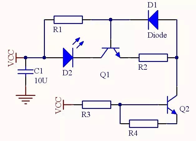
Circuit working principle: In the common-emitter amplifying circuit, the infrared light-emitting diode TLN205 is connected to the collector of the common-emitter amplifying circuit, and the diode connected to the base and the emitter functions as a temperature compensation. The control pin Vin is connected to the 68HC11E1 chip pin Vcc. When the control pin Vin has a signal input, the triode of the control circuit is turned on, and the entire circuit is turned on, and the infrared light emitting diode TLN205 emits infrared light.
Infrared receiving amplifier circuit
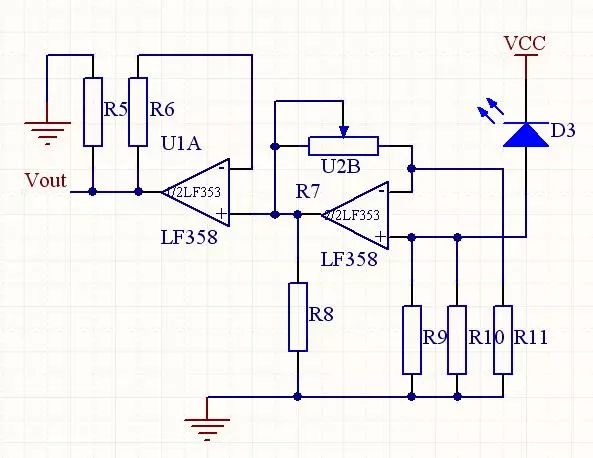
Circuit composition: The infrared receiving drive circuit is a module consisting of an infrared receiving tube TPS708 and two voltage series negative feedback analog operational amplifying circuits. The infrared receiving driving circuit is designed for two-pole amplification because in many cases, the input signal is very weak. To amplify such a weak signal enough to drive the load, it is impossible to use only one-stage circuit amplification, and must be multi-stage amplified to meet the amplification factor and other performance requirements.
The working principle of the circuit: the infrared light emitted by the infrared light-emitting tube TLN205 is received by the infrared receiving tube TPS708 after being reflected by the front obstacle, and the TPS708 generates a current corresponding to the light intensity. After the current is amplified by the LM358 in two stages, an analog voltage of 0~3V can be obtained at the output end, and the analog input of the 68HC11E1 MCU can be used for A/D conversion. Finally, the conversion result is displayed on the LED.
Quantitative analysis of operational amplifier circuit: We use negative feedback analog operational amplifier circuit because negative feedback has the advantages of improving gain stability, broadening the amplifier passband and reducing nonlinear distortion and noise, and negative feedback and corresponding output. Perform automatic adjustment.
Power circuit
Circuit composition: The regulated power supply consists of four parts: a transformer circuit, a rectifier circuit, a filter circuit, and a voltage regulator circuit. as the picture shows:
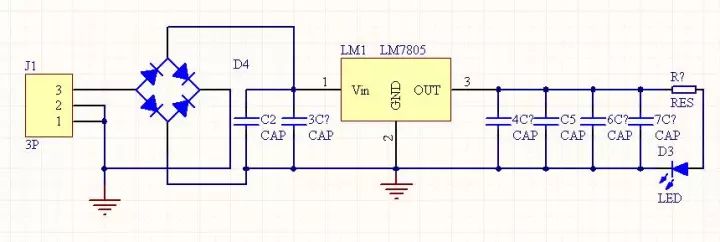
Circuit working principle: The circuit is an AC-DC conversion power supply circuit. First, the 220V AC power from the mains is changed to 9V AC power, and then the AC power is changed to the required DC power through the single-phase bridge rectifier circuit, and then filtered. The 7805 regulator turns the unstable DC voltage into a stable DC 5V output for use by the entire infrared ranging module.
Filter circuit
The voltage of the rectified output is a unidirectional pulsating voltage. Although it is DC, the pulsation is large. In order to obtain a smooth DC voltage waveform, a filter circuit must be used to improve the pulsation of the output voltage. The commonly used filter circuit has capacitive filtering and inductance. Filtering, complex filtering, etc., here capacitive filtering.
The single-phase half-wave rectification capacitor filter circuit is shown in the figure. Since the voltage across the capacitor cannot be abrupt, the voltage across the load will not be abrupt, so that the output voltage can be smoothed and the filtering purpose is achieved.
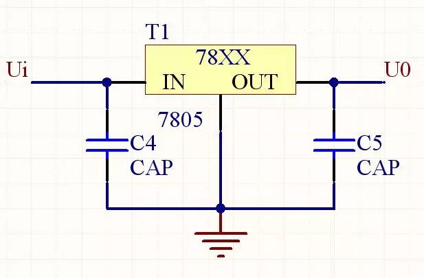
The DC power supply voltage obtained by the rectification and filtering circuit is relatively stable. When the grid voltage fluctuates or the load current changes, the output voltage changes accordingly. Electronic devices generally require a stable supply voltage. If the power supply voltage is unstable, it will cause zero drift of the DC amplifier, increase the AC noise, and reduce the measurement accuracy of the measuring instrument. Therefore, it is necessary to carry out voltage regulation. At present, the regulated power supply widely used in small and medium power devices has a parallel type regulated power supply, a series stabilized power supply, an integrated voltage stabilizing circuit and a switching type voltage stabilizing circuit.
Digital tube display circuit
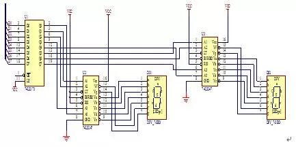
Circuit composition: LED dynamic display circuit shown in Figure 9, ASBUSA data output port PC0 ~ PC7 and 74LS373 data input port D0 ~ D7 connected, 74LS373 output high four bits Q4 ~ Q7 through 74LS247 decoding and DS2 connected, low The four bits Q0~Q3 are connected to DS1 through 74LS247 decoding, and the two LEDs can display the distance value of 10~80.
Circuit working principle: The BCD code of the output distance of the data output port PC0~PC7 of ASBUSA is latched by 74LS373. The high four bits Q4~Q7 are decoded by 74LS247 into corresponding break codes. The seven-digit code display tube displays ten digits. The lower four bits Q0~Q3 are decoded by 74LS247 into corresponding break codes. The seven-segment code display tube displays single digits, so the distance can be displayed by two LED display tubes.
Software module block diagram
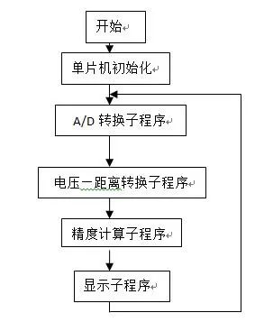
When the single chip receives the voltage signal transmitted by the infrared receiving circuit, the A/D conversion program converts the off-chip analog signal into a digital signal recognizable by the single chip, and converts the changed voltage into a voltage-distance conversion subroutine. distance. Finally, it is displayed on the LED display.
Thermometers include bimetallic thermometers, pressure thermometers and marine thermometers, which are suitable for detecting and controlling the liquid level of containers in shipbuilding and other industries.Bimetallic thermometer is a field detection instrument for measuring medium and low temperature. It can directly measure the temperature of liquid steam and gas medium in the range of - 80 ℃ - + 500 ℃ in various production processes. The main element of industrial bimetallic thermometer is a multilayer metal sheet composed of two or more metal sheets, which works based on the principle that two different metals have different expansion degrees when the temperature changes. It is composed of a bimetallic sheet wound into a circular bending shape. When one end is heated and expanded, the pointer is driven to rotate, and the working instrument will display the temperature value corresponding to the thermal potential.
Pressure Type Thermometer,Metalic Protector Thermometer,Flange Bimetallic Thermometer,Glass Tube Industrial Thermometer
Taizhou Jiabo Instrument Technology Co., Ltd. , https://www.taizhoujbcbyq.com