Large currents are often passed through the circuit, which causes many uncertainties in the circuit. In order to avoid damage to circuits or important devices caused by these factors, protection circuits have emerged. Protection circuits are especially important in inverters, which often require current conversion. This article will introduce you to several important protection circuit designs in the inverter power supply, and analyze and explain the principle in detail.
Anti-reverse protection circuit If the inverter does not have anti-reverse circuit, it will often have catastrophic consequences when the input battery is reversed. If it is burned, the fuse will be burned, and most of the circuit will be burnt. There are three main types of anti-reverse protection circuits in the inverter: anti-reverse protection circuit composed of anti-transverse Schottky diodes, as shown in Figure 1. 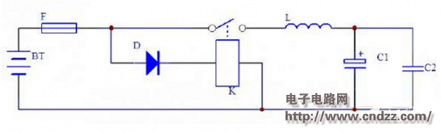
figure 1
As can be seen from Fig. 1, when the battery is reversed, the Schottky diode D is turned on and the F is burned. If the main conversion circuit of the push-pull structure is followed by the parasitic diode of the two push-pull switch MOS transistors, it is also equivalent to parallel with D, but the voltage drop is much larger than the Schottky, and the impact resistance against transient current is lower than that of Schott. The base diode D prevents the high current from passing through the parasitic diode of the MOS transistor, thereby protecting the two push-pull switch MOS transistors.
The anti-reverse protection circuit has a simple structure and does not affect the efficiency. However, after the protection, the fuse F is burned and needs to be replaced again to resume normal operation.
Adopting the anti-reverse protection circuit of the relay, the basic circuit is shown in Figure 2: 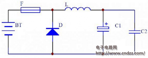
figure 2
It can be seen from the figure that if the battery is reversed, D is reversed, no current is passed through the coil of relay K, the contact cannot be closed, and the power supply of the inverter is cut off. This anti-reverse protection circuit has a better effect and does not burn the fuse F, but the volume is relatively large, and the life of the contacts of the relay is limited.
Adopt MOS tube anti-reverse protection circuit, the basic circuit is as shown in Figure 3: 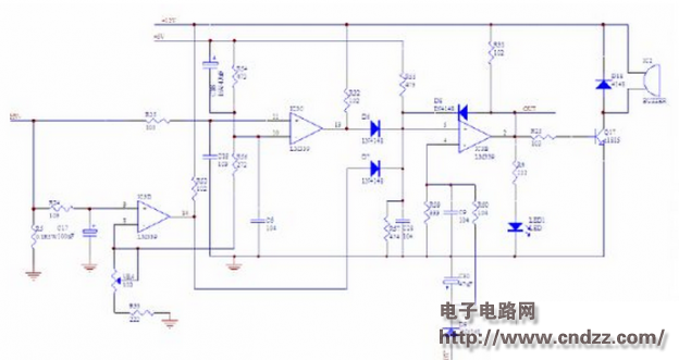
image 3
In Figure 3, D is a parasitic diode for anti-reverse MOS, which is easy to draw out. When the polarity of the battery is not reversed, D is positively biased, and the GS pole of Q is turned forward by the positive pole of the battery through F, R1, and D to return to the negative pole of the battery. The voltage drop after Q is turned on is much smaller than the voltage drop of D, so after Q is turned on, D will not get enough forward voltage and cut off;
When the battery polarity is reversed, D will be terminated due to reverse bias, and Q will also be terminated due to GS reverse bias, and the inverter cannot be started. This anti-reverse protection circuit has a long service life because it does not use a mechanical contact switch, and does not burn the fuse F like the anti-reverse protection circuit composed of a reverse Schottky diode. It is a certain loss when the MOS is turned on. It is sufficiently unobstructed to maintain relatively low losses through relatively large currents.
Undervoltage protection of the battery In order to prevent the battery from being over-discharged and damage the battery, we need to let the inverter stop working when the voltage is discharged to a certain voltage. It should be pointed out that if the undervoltage protection of the battery is too sensitive, it will start the impact load. Time protection. This makes it difficult for the inverter to start such loads, especially if the battery is not sufficiently charged. Please see the battery undervoltage protection circuit below.
It can be seen that this circuit can quickly establish the battery sampling voltage and delay protection due to the addition of D1 and C1. 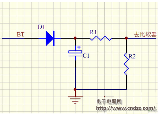
Figure 4
The design of the overcurrent short circuit protection circuit of the inverter:
As we all know, the overcurrent short circuit protection circuit of the inverter is very important in the safety of the inverter. If there is no overcurrent short circuit protection, the inverter is likely to be burnt due to overcurrent short circuit.
Let's first analyze the characteristics of the load. Most of the loads in real life are impact loads, such as incandescent bulbs. In the cold state, the resistance is much lower than when lighting, such as computer, TV, etc. The input AC power is rectified and filtered with a relatively large capacitor, so the inrush current is relatively large. There is also a motor inductive load such as a refrigerator. The motor needs to generate a relatively large torque from the static to the normal rotation, and the starting current is also relatively large.
If our inverter can only set a rated output power that can work for a long time, the load with a starting power greater than this rated output power cannot be started. This requires the inverter to be equipped according to the starting power. It is a waste. In practice, we design two protection points, rated power and peak power when designing an overcurrent short circuit protection circuit. The general peak power is set to 2-3 times the rated power. The rated power in time is not protected by long-term operation, and the peak power is generally only maintained for a few seconds to protect. The following is an example of an overcurrent short circuit protection circuit: 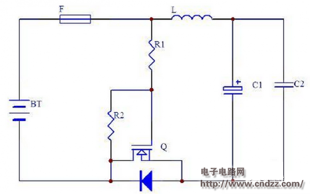
Figure 5
R5 is the high-voltage current sampling resistor of the full-bridge high-voltage inverter MOS tube source. We can understand that the magnitude of the high-voltage current basically determines the output power, so we use R5 to detect the high-voltage current. The two comparator units of the LM339 in Figure 5 are used for overcurrent and short circuit detection, respectively.
First look at the overcurrent protection circuit composed of IC3D and its peripheral components. The 8th pin of IC3D sets a reference voltage. The voltage is determined by R33, VR4, R56 and R54. U8=5*(R33+VR4)/(R33 +VR4+R56+R54). When the voltage on R5 passes the delay of R24 and C17, it exceeds the voltage of 8 pins. The output of the 14 pin is high level and is isolated to the 5 pin of IC3B through D7. 4 feet also do battery undervoltage protection, when the normal 5 pin voltage is lower than 4 feet, the over-current 5 pin voltage is higher than 4 feet, 2 pin output high level control after the high-voltage MOS is turned off, of course, can also be controlled before The MOS of the stage is turned off together. The role of D8 is overcurrent short circuit or battery undervoltage, positive feedback lock 2 feet is high.
Look at the short circuit protection circuit composed of IC3C, the principle is similar to the overcurrent protection, but the delay time is relatively short, the capacity of C19 is very small, and the speed of LM339 is very fast, the short circuit protection can be turned off within a few microseconds. , effectively protect the safety of high voltage MOS tubes. Incidentally, the short-circuit protection point is designed according to the parameters of the MOS tube ID, safety area and loop stray resistance. Generally speaking, the current is within the ID, and the action time is safe within 30 microseconds.
IGBT drive and short circuit protection
As a new type of power device, IGBT has the advantages of high voltage and current capacity, and the switching speed is much higher than that of the bipolar transistor and slightly lower than that of the MOS transistor. Therefore, it is widely used in various power supply fields. It is also widely used in the device.
The shortcoming of IGBT is that the collector current has a long tailing time - the off time is relatively long, so it is generally necessary to add a negative voltage to accelerate the shutdown when turning off; the second is the ability to resist DI/DT is relatively poor. If the MOS transistor is turned off quickly at a large short-circuit current like a protection MOS transistor, it may cause a high DI/DT at the collector, causing the UCE to induce a high voltage due to the influence of the stray inductance of the pin and the loop. And damaged.
The disadvantage of No.5 IGBT is that the collector current has a long tailing time - the off time is relatively long, so it is generally necessary to add a negative voltage to accelerate the shutdown when shutting down; the second is the ability to resist DI/DT. Poor, if the MOS transistor is turned off quickly at a large short-circuit current like a protection MOS transistor, it may cause a high DI/DT at the collector, which makes the UCE inductive due to the influence of the stray inductance of the pin and the loop. Damaged by high voltage.
The short-circuit protection of the IGBT is generally realized by detecting the saturation voltage drop of the CE pole. When the collector current is large or short-circuited, the IGBT exits the saturation region and enters the amplification region. As mentioned above, we can't turn off the IGBT directly and quickly. We can reduce the gate voltage to reduce the current of the collector to prolong the protection time and reduce the DI/DT of the collector. If the measure of reducing the collector voltage is not used to reduce the current of the collector, the short-circuit withstand of the IGBT with a saturation voltage drop of 2 V or less is only 5 μS. The short-circuit withstand of the 3V saturation voltage drop IGBT is about 10-15μS, and the short-circuit withstand of the 4-5V saturation voltage drop IGBT is about 30μS.
Another point, the time of the falling gate voltage can not be too fast, generally controlled at about 2μS, that is, in order to reduce the collector current from a large short-circuit current to 1.2-1.5 times the overload protection, it is generally controlled at about 2μS. Can not be too fast, if the short circuit disappears within the delay of the overload protection, it can be automatically recovered. If the overload protection current is still maintained, the IGBT is turned off by the overload protection circuit. Therefore, the short circuit protection of IGBT is generally matched with overload protection. The following is an application circuit diagram of TLP250 to increase the drive and short circuit protection of slow falling gate voltage: 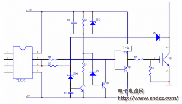
Figure 6
When the circuit in Figure 6 is working normally, the potential of the negative terminal of ZD1 is insufficient for ZD1 to turn on Q1 due to the conduction of D2; the negative terminal of D1 is high level, so Q3 is also cut off. C1 is not charged and the potential at both ends is zero. After the IGBT Q3 is short-circuited, it exits the saturation state, the collector potential rises rapidly, and D2 turns off from conduction. When the driving signal is high level, ZD1 is broken down, and C2 can make Q1 turn on for a short period of time, so that Q3 can be turned on for a short period of time, which avoids the false protection of the protection circuit during normal operation. After ZD1 is broken down, Q1 will be turned on after a short period of time due to the existence of C2. C1 starts to charge through R4 and Q1, and the negative potential of D1 begins to decrease. When the negative potential of D1 begins to drop to D1 and Q3be At the sum of the junction voltage drops, Q3 starts to conduct, and the base potentials of Q2 and Q4 begin to decrease, and the gate voltage of Q3 also begins to decrease. When C1 is charged to the breakdown voltage of ZD2, ZD2 is broken down, C1 stops charging, the process of falling gate voltage is also ended, and the gate voltage is clamped at a fixed level. The collector current of Q3 is also reduced to a fixed level.
This article explains the protection circuit in the inverter power supply from three aspects: anti-reverse connection, IGBT drive and short circuit, battery undervoltage, etc. Through the explanation of these three protection situations, I hope to help you protect the circuit in the inverter power supply. Have further understanding and understanding to facilitate your own design.
Dongguan Rongmao technology Co.,ltd , https://www.szroomoo.com