Part 2: Apply nanopower op amps to help current sensing
In the first part of this article series, we discussed the structure of offset voltage (VOS) and offset voltage drift (TCVOS) in DC gain, and how to select a nanopower op amp with ideal accuracy. Thus, the error in the amplified low frequency signal path is minimized. In the second part, we will review some of the basics of current sensing and describe how to use an op amp to minimize system power while providing accurate readings.
Current sensing
The designer implements current sensing for system protection and monitoring by placing a very small “shunt†resistor in series with the load and placing a current sense amplifier or op amp between the two. Although dedicated current sense amplifiers can provide excellent current sensing, a precision nanopower op amp is ideal if power is a particular concern.
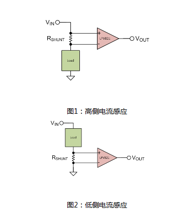
There are two places where the shunt resistor can be placed depending on the load: between the load and the power supply (Figure 1), or between the load and ground (Figure 2).

In both cases, the voltage across the shunt resistor is measured by an operational amplifier in order to sense the current with a known resistance. Using Ohm's law (Equation 1), the current consumption can be determined:

Where V is the voltage, I is the current, and R is the resistance.
Shunt resistors and op amps are chosen so that they have minimal effect on the performance of the circuit. When selecting the resistor, use the low value resistor according to the following two conditions:
Keep the voltage drop across the resistor as low as possible so that the negative side of the load is as close as possible to ground when the low side senses, or as close to the power source as possible when the high side senses.
Keep power consumption low. From Equation 2, it can be seen that since you are measuring current, it is an independent variable, so the resistance should be as small as possible:

Here's one thing to note: Because you're measuring current rather than minimizing it (as I did in Part 1), you must minimize the resistor value to minimize power consumption—this is in a DC gain configuration. The idea of ​​power management is the opposite.
Ultra-low-power current measurement technology is widely used in battery charging and monitoring of mobile devices, mobile phones and other terminal devices, and can also be used to ensure the normal operation of industrial Internet of Things applications.
How low can the pressure be reduced when choosing the resistance value? Simply put, the voltage drop across the resistor should be greater than the offset voltage of the op amp you are using.
Example
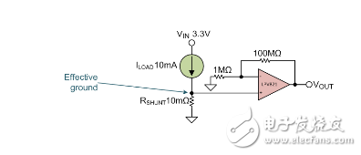
Suppose you want to perform a low-side differential current measurement (Figure 3) to ensure that there are no short circuits and open circuits in the system. For simplicity, this example uses simple numbers, ignoring parameters such as resistor tolerance.

Figure 3: Low-side differential current measurement
The power supply voltage is 3.3V. In the correct operation, the system draws a maximum current of 10 mA; you do not want to be effectively grounded and the load is higher than 100 μV. You must first understand that the voltage drop across the shunt resistor (due to the current) must be less than or equal to 100 μV.
If you use Equation 3 to determine the maximum shunt resistance:

The effective grounding is 100μV, as shown in Equation 4:

You must use an op amp that can detect this change in voltage drop to indicate if there is a fault. Since the system is in normal operation, the load current is within ±10% of its typical value. When the current changes by at least 10%, the op amp can detect the voltage change across the sense resistor.
If there is a fault (eg, open circuit, undervoltage due to low current, short circuit due to high current or brownout), Equation 5 shows the change in current (IΔ):

Equation 6 calculates the change in VSHUNT pressure drop:

In this example, I will choose the LPV821 zero-drift nanopower amplifier. Its zero-drift technology achieves a maximum offset voltage of only 10 μV, thereby detecting a fault condition. Zero-drift operational amplifiers are ideal for high-accuracy (<100μV) measurements. In addition, the LPV821 is also a nano power amplifier. You can keep it on and continuously sense the current accurately, with minimal impact on the system power budget.
Thanks for reading the second part of the series "How to Measure Precision with Nanopower Operational Amplifiers." We hope this series of articles will give you some insights on the benefits of using nanopower zero-drift op amps in DC gain and low-side current sensing applications.
Back Seat Headrest Pillow Phone Holder
Back Seat Headrest Pillow Phone Holder,Samsung Tablet Car Holder Back Seat,Car Back Seat Organiser With Tablets,Car Back Seat Tablet Holder
Ningbo Luke Automotive Supplies Ltd. , https://www.nbluke.com