In this article, the simplest IO port test is performed, and the LED light on the software control board is flashed.
Here are some of the main features of the I/O port:
• Open-drain enable/disable output pin separately
• Weak pull-up and pull-down of input pins can be individually enabled/disabled
• Monitors the selective input and generates an interrupt when it detects a change in the pin level state
• Can continue to work in sleep and idle modes
• Fast bit operation with CLR, SET and INV registers
Let’s take a look at the internal block diagram of the IO port, which looks very complicated.
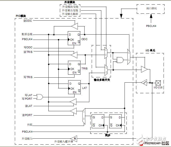
As a digital I/O, all port pins have up to 14 registers that are directly associated with their operation. The Data Direction Register (TRISx) determines whether the pin is an input or an output. If the data direction bit is 1, the pin is an input. After reset, all port pins are defined as inputs. When the latch (LATx) is read, the value in the latch is read; when the latch is written, the latch is written. When the port (PORTx) is read, the value of the port pin is read; when the port pin is written, the latch is written.
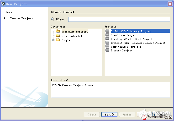
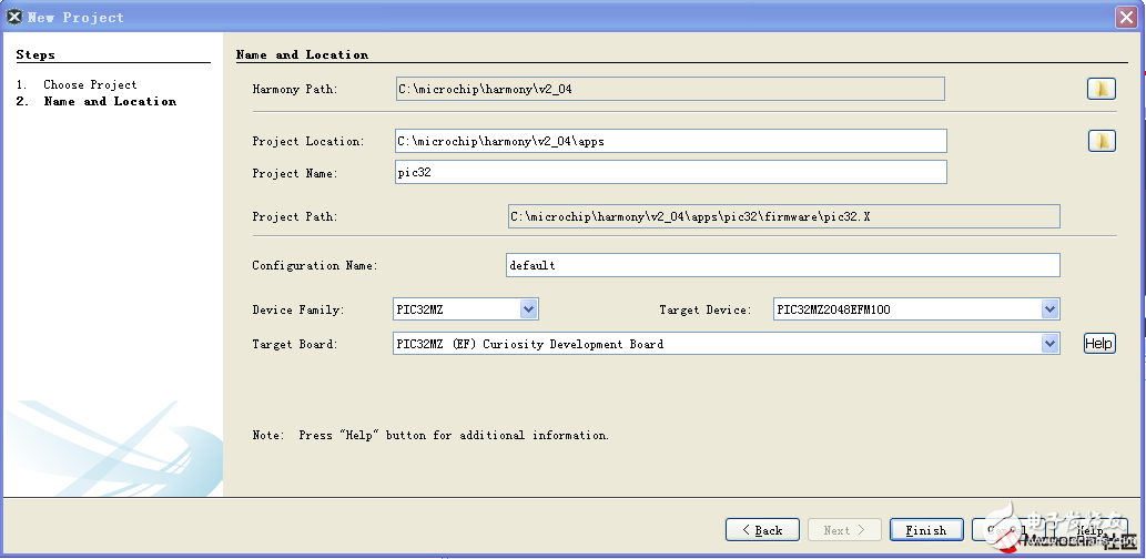
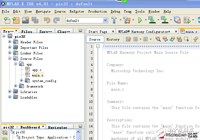
Open MPLAB X IDE and build a Harmony-based project. The files generated in Harmony are based on library operations. Simple, too many registers, too difficult to operate.
Configurability In Harmony's project, system_config.h, system_init.c, system_tasks.c, system_interrupt.c are reflected in several source files, as shown below:
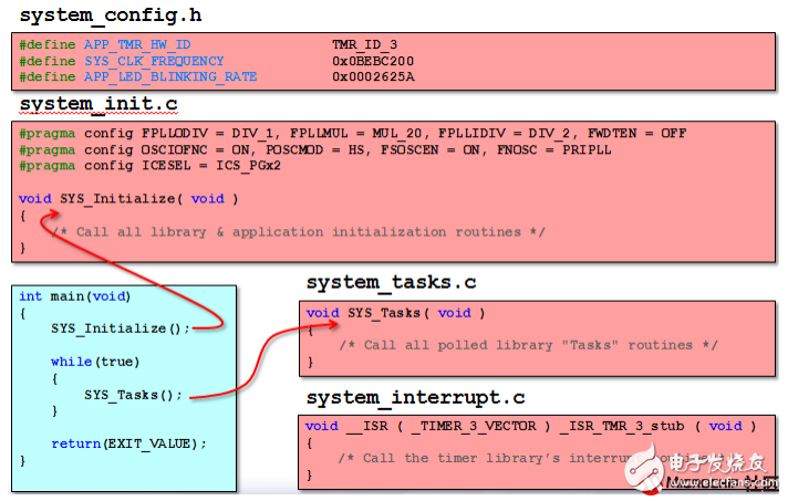
At the beginning of the design, Harmony fully considered the configurability of the project, allowing the same application code or software library to run on different hardware (or software) configurations, while also allowing MHC to be used, and the code structure is very Standard and easy to read.
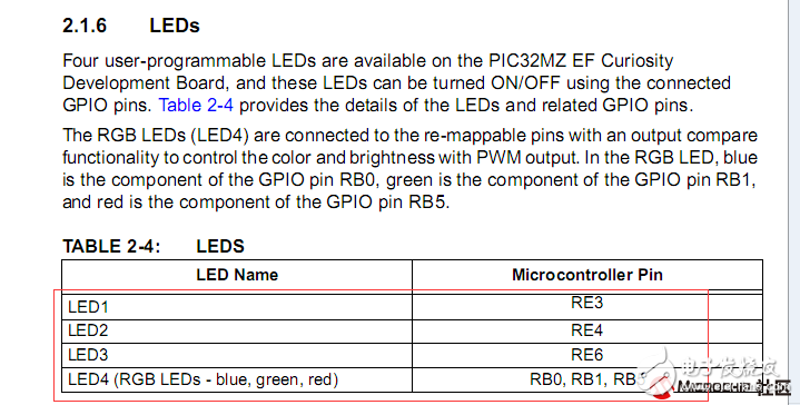
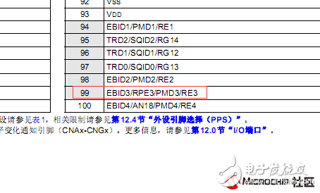
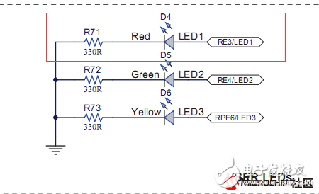
The clock and other configurations are taken as default. Let's take the RE3 port for experiment. The RE3 on the board controls one LED, which is high level and low level. Because the corresponding board configuration is selected, the default is correct.
Direct point generation project, open app.c file in the project
Because the main loop in mian is in the APP_Tasks function in app.c, add the following statement to the function.
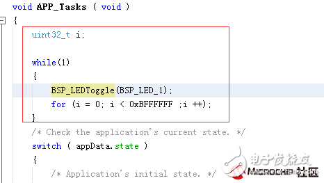
BSP_LEDToggle(BSP_LED_1); controls the level flip of the LED1 pin
The function of the delay is calculated according to the main frequency of 200MHZ, which is about 1S.
The function that BSP_LEDToggle jumps to is PLIB_PORTS_PinToggle. The function of this function is to flip which bit of the corresponding port. In the corresponding file ports_p32mz2048efm100.h file
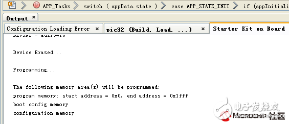
Compile the program, download, you can see the LED red light on the board is slowly flashing
Atx Connector,Female Inset Connector,Molding Solder Type Connector,Receptacle Solder Type Connector
Shenzhen Hongyian Electronics Co., Ltd. , https://www.hongyiancon.com