The SPWM (Sinusoidal PWM) method is a relatively mature one, and currently uses a wider PWM method. An important conclusion in the aforementioned sampling control theory is that the effects of the narrow impulses with equal impulses and different shapes are basically the same when they are applied to the inertia. The SPWM method is based on this conclusion. The PWM waveform, which is equivalent to the sine wave, and the SPWM waveform, which is equivalent to the sine wave, is used to control the on/off of the switching device in the inverter circuit to make the area of ​​the pulse voltage output. It is hoped that the output sine wave has the same area in the corresponding interval, and the frequency and amplitude of the output voltage of the inverter circuit can be adjusted by changing the frequency and amplitude of the modulated wave.
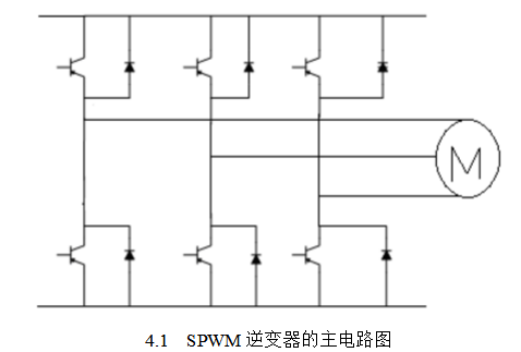
Structure of three-phase SPWM inverterThere is no essential difference between the SPWM inverter and the PWM inverter in the main circuit. The replacement of the thyristor in the voltage type PAM main circuit structure with the IGBT becomes the main circuit structure of the SPWM type inverter. In SPWM pulse width modulation, the instantaneous voltage switches direction at a very high speed and the output half-wave does not change direction. Therefore, the output voltage and the output current often do not coincide in direction. In this case, a freewheeling diode is needed to provide the opposite polarity of the voltage. Current channel. With the addition of a three-phase inverter bridge for freewheeling diodes, we have designed the basic main circuit of the SPWM inverter. Figure 4.1 shows the main circuit structure of the SPWM inverter. It consists of six IGBTs in a three-phase bridge structure with anti-parallel diodes on each bridge.

IGBT devices have their own unique drive circuits and protection circuits. In practice, IGBTs are usually not supplied in a separate form, but are provided in an intelligent module (IPM) that includes drive and protection circuits.
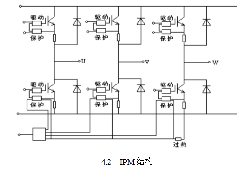
IPM not only provides drive circuits and protection circuits for IGBT devices, but also provides overheat protection for the entire module. In the case of relatively small capacity, IPM is often made into a multi-device structure, such as a six-cell or seven-cell structure. The six-cell structure integrates a complete SPWM inverter. Figure 4.2 shows the structure of a six-cell IPM. In addition to an inverter, the seven-unit IPM integrates the chopper components and auxiliary circuits for energy-consuming braking.

As seen in Figure 4.2, the six-unit module is the five main circuit terminals, namely the DC positive and negative input and the AC three-phase output terminal. There are also several control terminals for driving and protection, which are voltage-type interfaces that can be directly connected to a conventional control chip or connected by optical coupling. The driving terminal is an input terminal, and receives an external triggering device. The protection terminal is an output terminal, and a protection action signal is sent to the external controller while the protection circuit blocks the driving circuit. The main circuit terminals are usually in the form of terminal blocks, and the control terminals are usually in the form of concentrated jacks. The seven-unit IPM adds a main circuit terminal to which the braking resistor is connected and the corresponding control terminal.
When the capacity is relatively large, if the IPM still integrates the entire inverter, there are two disadvantages: First, the module's volume and weight increase, which makes it difficult to install and arrange, and is not conducive to heat dissipation; When the local components are damaged, the entire module needs to be replaced, and the cost of the large-capacity module is necessarily higher, thus increasing the maintenance cost.
Therefore, when the capacity is relatively large, the IPM is provided in two or one units. The two-unit IPM consists of all the components of an inverter bridge arm, namely two IGBTs, freewheeling diodes, drive and protection circuits. A unit IPM includes an IGBT and its freewheeling diode, drive and protection circuitry.
In the output main circuit of the inverter, a snubber circuit for continuously limiting the rate of voltage change is also required. The specific wiring principle of the driving circuit of the IGBT, the protection circuit, and other additional auxiliary circuits including the buffer circuit.
4 characteristics of SPWM inverterAlthough the square wave inverter is simple to implement, the harmonic content is too high, which is far from being suitable for most situations. It can only be used in very few occasions where the harmonic content is not high, but it has been applied since the sinusoidal pulse width modulation technology. After that, inverter technology has entered a new era, especially with the wide application of DSP chips this year, the development of inverters is digital and intelligent.
The SPWM inverter has the following features:
1. The circuit is simple, the main circuit structure is the same as the square wave inverter, but the output voltage, frequency and phase can be adjusted with only one half power level;
2. The uncontrollable rectifier bridge can be used to make the power factor of the system to the grid independent of the inverter output voltage value;
3. It can simultaneously perform frequency modulation and voltage regulation, which has nothing to do with the original parameters of the tributary link, and the dynamic response speed of the system has nothing to do with;
4, can get very small harmonic content, theoretically harmonic distribution on both sides of the carrier. SPWM is the abbreviation of Sine Pulse Width Modulation, which is sinusoidal pulse width modulation. It originated from the modulation technology in communication. The most basic principle is to use a reference wave, that is, a modulation wave, to go to a frequency N times its Compared with the triangular wave, a set of rectangular waves whose amplitudes are equal and whose pulse width changes according to the phase, amplitude and frequency of the modulated wave can be obtained. Then, the waveform is used to control the opening and closing of the switching tube, and the high voltage of the same waveform can be obtained. pulse. Since the reference wave is usually a sine wave, this technique is often referred to as sinusoidal pulse width modulation, or SPWM technology.
There are many different versions of DIN Connectors. The name of each type comes from the number of pins the connector has (3-pin DIN, 4-pin DIN, etc.) Some of these pin numbers come in different configurations, with the pins arranged differently from one configuration to the next.
DIN cable connector 3-pin, 4-pin, 5-pin, 6-pin, 7-pin, 8-pin degree 180, 216, 240, 262, 270
DIN cables, DIN connector, telephone cable, computer cable, audio cable
ETOP WIREHARNESS LIMITED , https://www.oemwireharness.com