Microstrip bandpass filters are commonly used in satellite communications, medical, and wireless communication systems. With the rapid development of modern technology, higher requirements are placed on the performance of RF transceiver front-end filters in various systems. The miniaturization and high performance of microstrip filters have become hot and difficult. The dual-mode resonator has its unique advantages when it is designed for microstrip filters. The dual-mode resonator has a pair of degenerate modes. By adding a perturbation in the resonator, the two degenerate modes are separated, which is equivalent to two. A tuning circuit [1], that is, a dual-mode resonator can reduce the inherent order of the filter by half, so that the filter structure is simple, the size of the filter is reduced [2], and the filter structure is more compact.
Microstrip patch resonators are widely used in the design of filters and antennas because of their ease of design, processing, low cost, and mass production. In 1972, Wolff first designed the microstrip dual-mode filter with a ring patch. After long-term research and development, the existing patch filter structure has a triangular shape, a square ring shape, a square shape and the like. Chen Xinwei et al. [3] added a T-type perturbation method to a semi-circular ring resonator, resulting in an insertion loss of less than 0.32 dB in the passband and an out-of-band attenuation greater than 20 dB; AVINASH KG et al. [4] by loading a quarter-wavelength open circuit The combination of stubs and square patches improves the selectivity of the passband on both the high and low frequencies; Zhu Lei [5] reduces the filter by opening a T-shaped cross slot on the square patch. Size and return loss.
Huang Xiaodong et al [6] used a dual-mode ring resonator loaded with distributed capacitors to maintain a large amount of coupling while maintaining the miniaturization of the resonator. Sun Shoujia et al. [7] affect the center frequency of the passband by loading a pair of open branches, and use source and load coupling to enhance the coupling strength between the source and the load, thus introducing a new transmission zero.
This paper starts with a square ring patch structure and uses a stepped impedance square ring resonator to form a dual mode microstrip filter, because the square ring resonator itself is not only easy to achieve cascade coupling, but also easy to reduce radiation loss. A square chamfer is introduced as a perturbation on the square ring resonator. The input/output and the resonator are directly fed and optimized. The optimized filter center frequency is 2.2 GHz, and the maximum return loss is better. 47.5 dB, 3 dB relative bandwidth is 18.2%. Moreover, the filter has attenuation poles on both sides of the passband, which improves the stopband rejection performance.
Analysis of a square dual mode filter
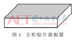
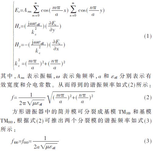
Figure 1 is a structural diagram of a square patch resonator. According to the theoretical study of the patch resonator by Wheeler's cavity model [8], the upper and lower surfaces of the patch resonator can be equivalent to an ideal electric wall, and the remaining surfaces can be equivalent. For an ideal magnetic wall, the field distribution in a square patch resonator is as shown in equation (1):
2 filter design
2.1 Structural analysis of the filter
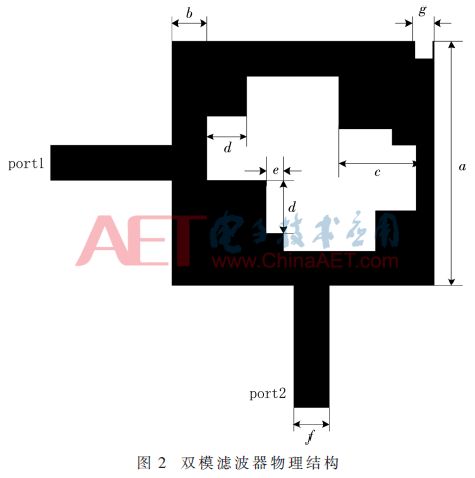
The square ring patch filter structure of this design is shown in Figure 2. The filter consists of a stepped impedance square ring resonator and a square chamfer perturbation. The addition of the stepped impedance causes the current inside the resonator to grow longer, because the loop circumference of the current is proportional to the operating wavelength of the resonator, so the resonant frequency of the resonator is reduced [9], and the filter is reduced. size of. The square chamfer in the upper right is used as a perturbation to separate the orthogonal degenerate modes of the square ring resonator. A mode with the same resonant frequency but different field distribution is usually called a degenerate mode. The feeder adopts the direct coupling method instead of the slot coupling method, which reduces the radiation loss and improves the production precision while achieving strong coupling [10]. It can be seen from Fig. 2 that the band pass filter proposed in this paper has a simple structure and is easy to be processed.
2.2 Filter performance
Using the microstrip dual-mode filter constructed above, the specific design specifications are: center frequency f0=2.2 GHz; passband is 2.0 GHz to 2.4 GHz (FBW=18.2%); in-band insertion loss is less than 0.47 dB; sideband suppression : The suppression of the low-end stopband from 1.68 to 1.72 GHz is more than 35 dB, and the suppression of the high-end stopband from 2.55 to 2.66 GHz is more than 25 dB; the volume is 25 mm × 25 mm × 0.81 mm.
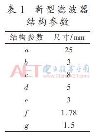
Using high-frequency electromagnetic field simulation software HFSS for simulation, the dielectric plate material used in this paper is Rogers RO4003, its relative dielectric constant is 3.55, the thickness of dielectric substrate is h=0.81 mm, the thickness of metal layer is 0.017 mm, 50 Ω microstrip feeder The line width is 1.78 mm. The filter center frequency designed in this paper is 2.2 GHz, thus setting the original parameters of the filter structure a=25 mm, b=3 mm, c=8 mm, d=5 mm, e=3 mm. In the case of other dimensions of the fixed resonator, the effect of changing the ring width b on the filter frequency response characteristics is analyzed, and the ring width is set to 2 mm, 3 mm and 4 mm, respectively, and the full-wave simulation analysis of the filter is obtained. The frequency response curve is shown in Figure 3.
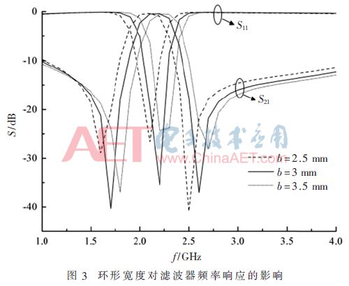
It can be seen from Fig. 3 that there are attenuation poles on both sides of the filter passband. As the ring width increases, the return loss in the passband decreases, and the attenuation poles on both sides move to the right, causing the center frequency to shift to the high frequency. Moving, and the attenuation pole is also reduced, which improves the filter selection performance.
In order to determine the influence of the square cut angle dimension g on the filter frequency response characteristics, the side lengths of the square chamfers are set to 1 mm, 1.5 mm and 2 mm, respectively. The frequency response curve obtained after full wave analysis of the filter is shown. 4 is shown.
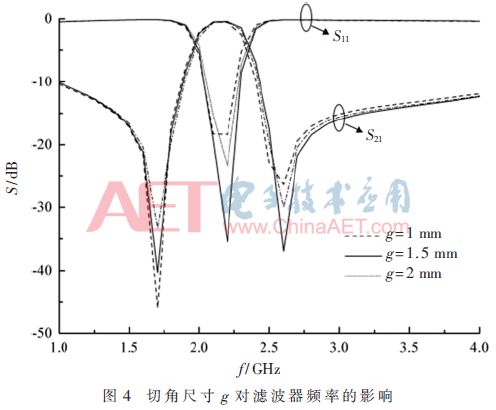
It can be seen from Fig. 4 that the square chamfer size has an influence on the return loss S11 in the passband and the attenuation pole on the left side of the passband. As the g decreases, the left attenuation pole decreases significantly. Therefore, the appropriate chamfer size should be selected when actually designing the filter.
In order to determine the effect of the high impedance length in the stepped impedance on the filter frequency response characteristics. Different high-impedance lengths are set in the step-step impedance respectively, and the frequency response curve of the dual-mode filter can be obtained by performing full-wave analysis on the filter as shown in FIG. 5 and FIG. 6.
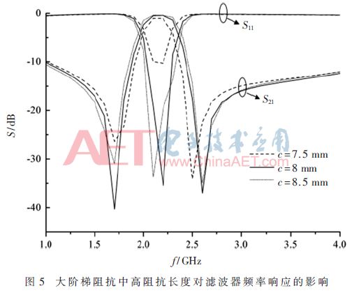
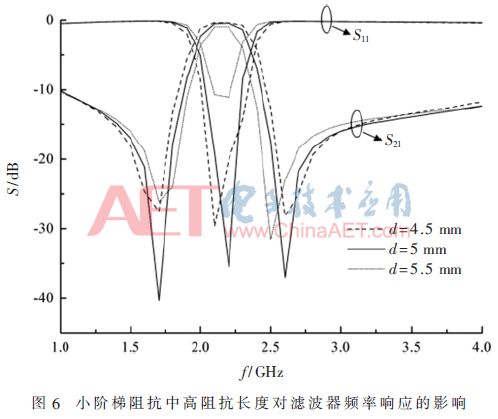
It can be seen from Fig. 5 and Fig. 6 that the high impedance length in the step impedance has a great influence on the attenuation poles and return loss on both sides of the passband, and the attenuation pole is significantly reduced as the high impedance length increases. The resistance of the stop band is improved; in the large step impedance, as the high impedance length increases, the return loss decreases, and when it exceeds a certain value, it increases, so when designing the filter, the appropriate height should be selected. Impedance length.
It can be seen from the above analysis that in the design of the filter, the frequency and bandwidth of the filter can be adjusted by adjusting the ring width, and then the position of the transmission zero on both sides of the pass band can be adjusted by adjusting the square cut angle size and the high impedance length in the step impedance. Size, which in turn optimizes the return loss and insertion loss characteristics of the filter.
3 filter test
According to the above analysis and design, the final optimization parameters corresponding to the dual mode filter shown in Fig. 2 are obtained by adjustment and optimization as shown in Table 1.
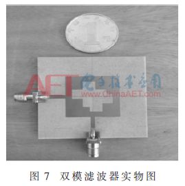
The physical map obtained after the filter processing in this paper is shown in Fig. 7. The S parameters of the filter are tested by the network analyzer. The simulation results are shown in Fig. 8. The 3 dB bandwidth of the filter is 400 MHz (relative bandwidth is about 18.2%), and the two poles are located at 1.7 GHz and 2.6 GHz, respectively. The simulation results are basically consistent.
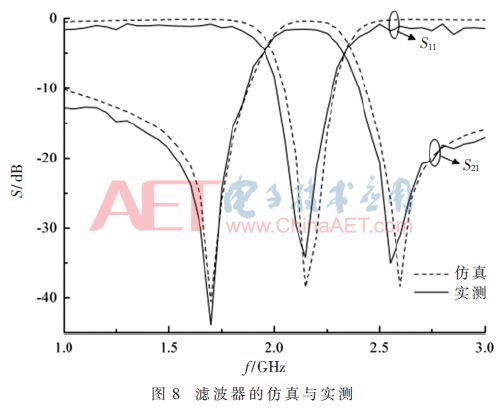
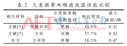
Finally, the relevant parameters of several types of microstrip dual-mode filter structures are listed in Table 2, and compared with the structure designed in this paper. It can be seen from Table 2 that the dual-mode microstrip filter proposed in this paper is simpler in structure and easier to process than the literature [7]; it is better in performance than the literature [3].
4 Conclusion
In this paper, a new square-ring patch filter structure is proposed. By introducing a square chamfer on the resonator to excite the degenerate mode, the filter has good in-band characteristics; loading the stepped impedance on the resonator can The filter has a transmission zero on each side of the passband; the orthogonal direct feeding method is used to reduce the radiation loss, improve the fabrication precision, improve the practical value of the filter, and further optimize the performance of the filter. Used in S-band satellite communication transceiver system.
Insulated Terminals,Terminals,High-quality insulated terminals
Taixing Longyi Terminals Co.,Ltd. , https://www.longyicopperterminals.com