(1) Rotary converter unit - consists of an AC motor and a DC generator to obtain an adjustable DC voltage.
(2) Static Controllable Rectifier - Use a static controlled rectifier to obtain an adjustable DC voltage.
(3) DC chopper or pulse width modulation converter - powered by a constant DC power supply or an uncontrolled rectifier power supply, using power electronic switching devices to chop or pulse width modulation to produce a variable average voltage.
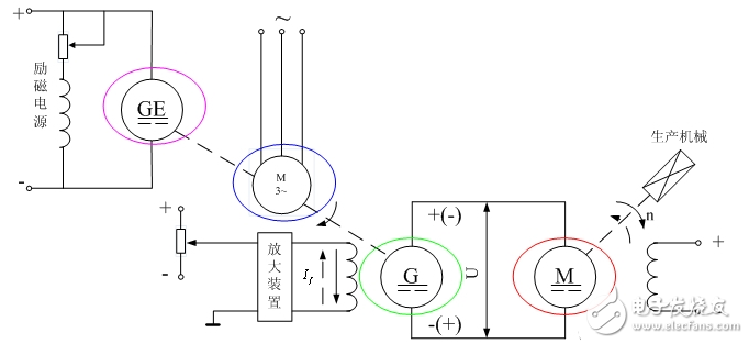
The commonly used controllable DC power supply is divided into the following cases due to the different types of power supply: 1. Rotary converter unit controllable converterThe controllable converter device used in the early days is a rotary converter unit, and the DC motor speed control system powered by it is shown in Fig. 1.

Figure 1 Rotary converter unit
In the figure, the AC motor (shown by the blue circle in Figure 1) is the prime mover, and the rotational speed is substantially constant during operation. The DC generator G (the green circle in Fig. 1 appears in seconds) dragged by it supplies power to the armature of the DC motor M (shown by the red circle in Fig. 1) that requires speed regulation. GE (the purple circle in Figure 1) is a small DC generator that can be coaxially connected to the AC motor or DC generator G as shown in the figure, or a small AC motor can be used to drag it. Its role in the system is to provide a small-capacity DC power supply for the stator excitation of the DC generator G (shown by the green circle in Figure 1) and the DC motor M (shown by the red circle in Figure 1), so it is also called GE is an excitation generator.
For a DC generator, the stator needs DC excitation, and the external force torque causes the rotor to rotate, thereby generating a dynamic electromotive force. For a DC motor, the stator needs DC excitation, and the working DC power is externally connected to the rotor to generate torque on the rotor.
The DC speed control system powered by the rotary converter unit can be referred to as the GM system for short. Changing the magnitude of the excitation current If of G also changes the output voltage U of G, which in turn changes the rotational speed of M of the direct current motor.
When the speed regulation performance of the system is not high, the amplification device in the figure can be used. If is directly provided by the excitation power supply GE, the higher closed-loop speed regulation system should generally have an amplification device. If the direction of If is changed, the polarity of U and the direction of rotation of the direct current motor M will change. Therefore, the reversible operation of the GM system is very easy to implement.
How can the above direction of changing If can be achieved?
The GM system was widely used in the 1960s, but because of its short equipment, large size, low efficiency, and high operating noise, it was replaced by a more economical and reliable thyristor rectification controllable converter.
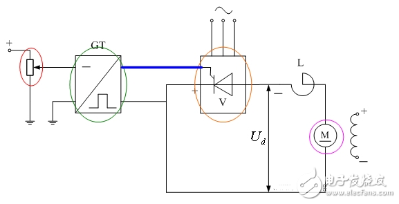
2. Thyristor rectifier controllable converter device
Figure 2 Thyristor rectifier
The DC speed control system of the thyristor rectifier device is shown in the figure. The GT (shown by the green circle in Fig. 2) is the trigger device of the thyristor, and V (the orange circle in Fig. 2 appears) is a thyristor rectifier, which is combined into a controllable DC power supply. The controllable DC power supply supplies the DC motor to the DC motor M (shown by the purple circle in Figure 2). This type of DC speed control system is referred to as the VM system.
By changing the input signal of the GT (the red circle in Figure 2), the phase of the output pulse (the blue line in Figure 2) can be changed. The pulse of different phases is input to the rectifier V, which can make the output voltage of the rectifier Ud. The size changes to change the speed of the motor M.
The power amplification factor of the thyristor controllable DC power supply is two to three orders of magnitude higher than that of the rotary converter unit, and the system reaction speed is also more than two orders of magnitude higher.
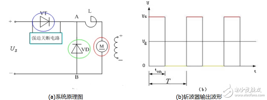
3, DC chopperFigure 3 (a) is a schematic diagram of a DC chopper-motor speed control system using a thyristor as a switch.

Figure 3 DC chopper
When the thyristor VT (the blue circle in Fig. 3 appears) is triggered to conduct, the power supply voltage Us is applied to the armature of the motor M (the red circle and the line segment in Fig. 3); when the VT is under the control signal When the power-off circuit is turned off by forcing the shutdown circuit (shown in the light blue frame in Figure 3), the power supply is disconnected from the motor armature, and the motor continues to flow through the diode VD (shown by the green circle in Figure 3). At this time, A, B The voltage between the two points (ie, the ends of the armature) is close to zero (the yellow line segment in Figure 3 appears). If the thyristor VT is repeatedly turned on and off, the voltage waveform between A and B can be obtained as shown in (b). From the waveform, it is as if the power supply voltage Us was formed after a period of time (from ton to T), which is the origin of the name chopper.
Based on the characteristics of the voltage waveform, pulse width modulation (PWM) control, pulse frequency modulation (PFM) control and two-point control are often used in the electric drive system. Among them, pulse width modulation is the most widely used. In the speed control system, it is combined with the motor to form a PWM-motor system, referred to as a PWM speed control system or a pulse width speed control system.
DC choppers are currently widely used in electric traction equipment and high performance small servo systems.
SHENZHEN CHONDEKUAI TECHNOLOGY CO.LTD , https://www.szsiheyi.com