Semiconductor lighting is regarded as the third generation of lighting devices, which can be used in large-screen color display, special lighting, traffic signals, multimedia display LCD backlights, optical communications and other fields. Because it is a cold light source, semiconductor lighting not only has no pollution to the environment, but also has a power saving efficiency of more than 90% compared with traditional incandescent lamps and fluorescent lamps.
Semiconductor technology is also known as LED lighting technology in the industry, mainly including LED core technology, LED packaging technology and LED application technology. In recent years, LED chip technology has developed rapidly under the support of various countries, and the size of LED chips is getting bigger and bigger. The power is getting bigger and bigger, the power of a single LED chip can be made into a large 3W LED installation technology, and the size, shape and function of the packaged product are continuously developed and improved. It provides ample space for the design and manufacture of LED application technology while highlighting the diversity, flexibility, complexity and breadth of LED lighting technology.
The United States, Japan, South Korea and other countries and regions have launched semiconductor lighting plans in recent years, investing heavily in research and development. The world's three major lighting manufacturers - General Electric, Philips, Osram have been working with semiconductor companies to form a semiconductor lighting company. Under the initiative of several units such as the US Department of Energy and the US Optoelectronic Industry Development Association, Sandia National Laboratories began drafting the US semiconductor lighting technology development blueprint (2002-2020) in March 2001, aiming at the next generation of lighting. Planning provides technical arguments.
At the same time, Japan is also vigorously developing semiconductor lighting technology, which is typically the “Japan 21st Century Lighting Projectâ€, which is developed by the Japan Research and Development Center of Metals and the New Energy Industry Technology Development Organization (NEDO). ) A national plan initiated and organized for a period of five years. The program's participating institutions include four universities, 13 companies and an association aiming to increase the energy efficiency of lighting to traditional fluorescent lamps by using long-lived, thinner and lighter GaN efficient blue and ultraviolet LED technologies. Double (ie reduce the energy consumption of traditional lighting) and reduce the production of CO2. The entire plan's financial reserves were 6 billion yen.
Basic principles of semiconductor lightingThe most popular ones today are the application research of III-nitride light-emitting diodes such as InGaN, AlGaN, and GaN. The blue-green, blue, and ultraviolet light emitted by these tubes can be combined with red and green light-emitting diodes to form white light. Can be used directly to stimulate the phosphor to emit white light. Therefore, nitride light-emitting diodes are the first choice for white light sources. They will replace incandescent, fluorescent and other light sources and become the mainstream of future white lighting. Therefore, nitride light-emitting diodes have become a new generation of semiconductor optoelectronic devices, and will play an irreplaceable role in future energy-saving lighting.
At the same time, the luminous efficiency of LED devices is increasing by about 10 times every 10 years. In particular, GaN blue-green LEDs, which appeared in the early 1990s, have developed particularly rapidly, with luminous efficiency increasing by a factor of 100 in 10 years. It is also because of the emergence of GaN-based blue-green LED devices that make up for the shortcomings of LED devices in terms of short wavelengths, not only achieving full-color LED display, but also making LED white light illumination possible. With the rapid development of material growth and fabrication technology, LED devices have evolved from early indications (typical injection currents of 20 mA) to power types (currently typical injection currents of 350 mA), and applications have expanded from stateful representation to nightscape decoration. Traffic signal indication, car lighting, large screen full color display, etc.
The semiconductor illumination source with GaN-based power blue LED as the core is considered as the third generation illumination source after incandescent lamp and fluorescent lamp, and has become a research hotspot in the field of optoelectronics at home and abroad. Compared with the traditional light source, the semiconductor light source operating in full solid state has the potential advantages of high luminous efficiency, long life, small volume, fast response, vibration and shock resistance, environmental protection, safe use, etc., and has broad application prospects.
The semiconductor light-emitting diode is the core of semiconductor illumination. The principle of illumination is shown in Figure 1. Under the condition of forward bias of the pn junction, the electrons are injected into the active region of the device to recombine spontaneous emission and convert the electrical energy into light energy. . Since the 1950s, the wavelength of LEDs has expanded from infrared to visible and ultraviolet. The wavelength of the LED device is determined by the bandgap energy of the material. The gallium nitride-based LED material is a direct bandgap semiconductor material, including aluminum nitride (AIN), indium nitride (InN), gallium nitride (GaN), and alloys thereof. Bandgap energy covers the visible, ultraviolet and deep ultraviolet bands.
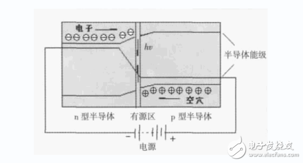
Figure 1 LED working principle diagram
There are three ways to implement semiconductor lighting:1) Based on the principle of three primary colors, white light is synthesized by using three primary color LEDs of red, green and blue, as shown in Fig. 2(a);
2) using ultraviolet LED to excite the three primary color phosphors, and the light emitted by the phosphors synthesizes white light, as shown in Fig. 2(b);
3) The blue light phosphor is excited by the blue LED to realize the binary mixed white light, as shown in Fig. 2(c).
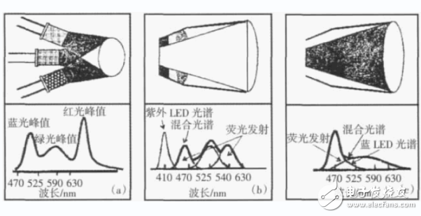
Figure 2 3 ways to achieve white solid-state lighting
(a) three primary color LEDs to synthesize white light;
(b) ultraviolet LED excitation of the three primary color phosphors to achieve white light;
(c) Blue LEDs excite yellow phosphors to achieve binary mixed white light
By using three primary color LEDs to mix white light, not only can the ideal white light spectrum be realized, but also the color of the light source can be adjusted. However, the performance of the three primary color LEDs is strict, and the peripheral circuits such as the driving circuit are also complicated. Therefore, the cost performance is high, but it is applicable. In the case of high color requirements. The use of ultraviolet LEDs to excite trichromatic phosphors to achieve white light is currently lacking high-power UV LEDs and high-efficiency, high-reliability UV phosphors, so it is not yet practical. The blue phosphor LED excitation method has a mature phosphor and a high-efficiency, high-reliability blue light source. Although the color rendering index is slightly insufficient, the scheme has the highest lumen efficiency and is currently widely used. Unless otherwise specified in the following discussion, semiconductor illumination refers to the technical approach of exciting yellow phosphors with blue LEDs.
1.0mm (.039″) Pitch Pin Headers
Overview
Antenk offers a variety of high quality and competitively priced 1.0mm pitch single, dual, three, quad row pin (male) headers used in many board-to-board PCB connections, fitting small-sized, densely-packed devices.
This low-profile component is made from high-temperature thermoplastic and is offered with several means of connections and mounting styles such as through-hole (THM) or surface mount (SMT) and can be in vertical (straight), elevated or at a right angle configuration/orientation dissipating current of about 1.0 A or less.
The pin (male) header is generally mated with receptacle or stackable header connectors (female sockets). This types of pin headers are suitable for PCB board to board connection or for signal transmission application.
Applications of 1.0mm Pitch Pin Headers
Its small size is most suitable for PCB connections of small equipment and devices such as WiFi equipment, gaming consoles, measurement instruments, and other equipment in need of a special interface to become interconnected
Mount Type: Through-hole vs Surface Mount
At one side of this pin header is a series of pins which can either be mounted and soldered directly onto the surface of the PCB (SMT) or placed into drilled holes on the PCB (THM).
Through-Hole (Poke-In)
Best used for high-reliability products that require stronger connections between layers.
Aerospace and military products are most likely to require this type of mounting as these products experience extreme accelerations, collisions, or high temperatures.
Useful in test and prototyping applications that sometimes require manual adjustments and replacements.
1.0mm vertical single row header, 1.0mm vertical dual row header, 1.0mm Elevated single row pin header, 1.0mm Elevated dual row pin Header, 1.0mm Right-angle single row header and 1.0mm Right-angle dual row header are some examples of Antenk products with through-hole mount type.
Surface-Mount
The most common electronic hardware requirements are SMT.
Essential in PCB design and manufacturing, having improved the quality and performance of PCBs overall.
Cost of processing and handling is reduced.
SMT components can be mounted on both side of the board.
Ability to fit a high number of small components on a PCB has allowed for much denser, higher performing, and smaller PCBs.
1.0mm Right-angle Dual Row pin header, 1.0mm SMT Single row pin header, 1.0mm SMT Dual row pin header and 1.0mm Elevated Dual Row Pin Header are Antenk`s SMT pin headers.
Soldering Temperature for 1.0mm Pitch Pin Headers
Soldering SMT pin header can be done at a maximum peak temperature of 260°C for maximum 60 seconds.
Pin-Type: Vertical (Straight) and Right-Angle
1.0mm pitch headers may be further classified into pin orientation as well, such as vertical or straight male header or right-angle male header.
Vertical or Straight Pin (Male) Header Orientation
One side of the series of pins is connected to PCB board in which the pins can be at a right-angle to the PCB surface (usually called "straight" or [vertical") or.
Right-Angle Pin (Male) Header Orientation
Parallel to the board's surface (referred to as "right-angle" pins).
Each of these pin-types have different applications that fit with their specific configuration.
PCB Connector Stacking
Elevated Pin Header Orientation
Elevated pins aka Stacked Pins or Mezzanine are simply stacked pin headers providing an exact distance requirement between PCBs that optimizes electrical reliability and performance between PCB boards.
Profile Above PCB
This type of configuration is the most common way of connecting board-to-board by a connector. First, the stacking height is calculated from one board to another and measured from the printed circuit board face to its highest insulator point above the PCB.
Single, Dual or Multiple Number of Rows
For a 1.0mm straight or vertical male pin header, the standard number of rows that Antenk offers ranges from 1 to 2 rows. However, customization can be available if 3 ,4 or n number of rows is needed by the customer. Also, the number of contacts for the single row is about 2-50 pins while for dual row, the number contacts may vary from 4-100 pins.
Pin Material
The pins of the connector have been designed with copper alloy. With customer`s demand the pins can be made gold plated.
Breakaway design
The pin headers are also equipped with a breakaway design making them fully compatible with their female receptacles.
Custom 1.0mm Pitch Pin Headers
Customizable 1.0 mm pitch pin headers are also available, making your manufacturing process way faster as the pins are already inserted in the headers, insulator height is made at the right size and the accurate pin length you require is followed.
Parts are made using semi-automated manufacturing processes that ensure both precision and delicacy in handling the headers before packaging on tape and reel.
The tape and reel carrier strip ensures that the headers are packaged within accurately sized cavities for its height, width and depth, securing the headers from the environment and maintaining consistent position during transportation.
Antenk also offer a range of custom Tape and reel carrier strip packaging cavities.
Male Header Pins,1.0Mm Male Header,1.0Mm Pin Header,1.0Mm Male Header Pins, 1.0mm THM Male Header, 1.0mm SMT Male Header
ShenZhen Antenk Electronics Co,Ltd , http://www.coincellholder.com