In the industrial control system dominated by the upper computer or plc, especially in the control of various mechanical equipment, the combination application of PLC, touch screen, servo motor driver, servo motor or stepper motor driver and stepping motor is often seen. . For the servo motor and stepper motor, because the structure is simple, the principle is not too complicated. When you see the object and cooperate with the application, you will understand. However, it is difficult to know the "original" of the structure and circuit of the motor driver, limited to various conditions.
Due to the working relationship, I took over a stepper motor driver that needs to be repaired. Because of the need of maintenance, I have mapped the whole circuit diagram of the stepper motor. Under the navigation, I know that the stepper motor driver is a matter of course. Here, the whole picture of the whole machine is dedicated to everyone.
A total of 4 pictures of the whole machine:
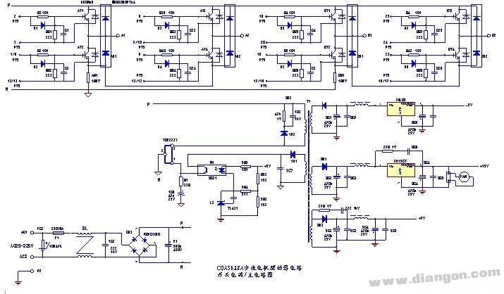
The first picture: the main circuit and switching power supply circuit driven by the stepper motor. The form of the power output circuit of the stepper motor driver is similar to that of the main circuit of the frequency converter. Each way is made up of two IGBT tubes as push-pull output, and diodes are also connected in parallel on the tube to provide reverse current path, thus protecting the safety of IGBT tubes. The overcurrent protection signal of the IGBT tube is obtained by two resistors of AR1 and BR1. The two resistors convert the current signal flowing through the IGBT tube into a voltage signal, which is processed by the post-stage protection circuit and sent to the single chip microcomputer. The +5V output of the switching power supply acts as the power supply for the microcontroller. In addition, +5V and -5V are also supplied as dual circuits for the protection circuit. A +15V power supply is converted into a four-way 15V power supply via PIC and PT1 for four-way drive circuits.

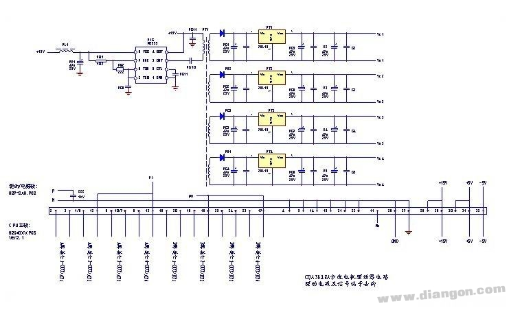
The second picture: the source of the drive power and terminal signals. The +15V power supply from the power supply board is oscillated and inverted by the NE555 time base circuit, and the four secondary windings of the switching transformer PT1 output four sets of mutually isolated 15V DC voltages for power supply of the driving IC;

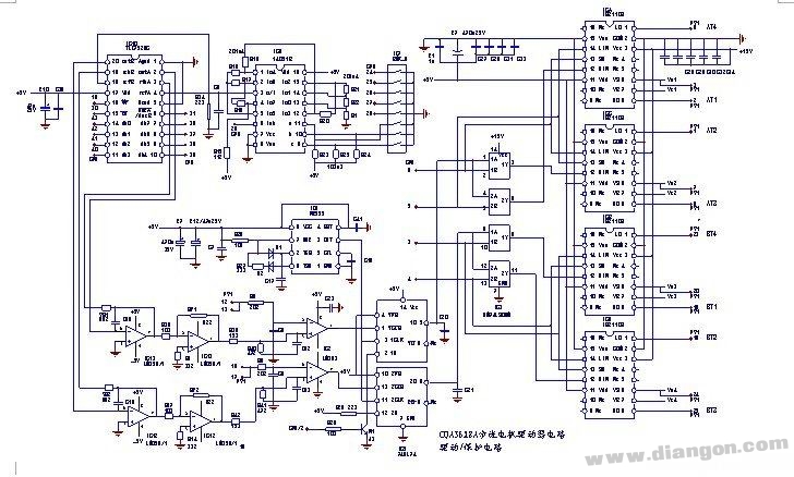
The third picture: the pulse drive circuit of the stepper motor driver and the operating current setting circuit of the step motor. The driver IC adopts the IS2110S dedicated driver chip. The four-channel pulse signal output by the single-chip microcomputer is processed by the 74LS08 42-input and gate circuit, and then sent to the four IS2110S driver circuits. After the photoelectric isolation and power amplification, the inverter power circuit is sent and discharged. Input a step pulse to the step motor;

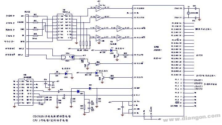
The fourth picture: the circuit diagram of the CPU (single chip) circuit and the control terminal. The stepping motor driver generates a four-way pulse signal from a single-chip microcomputer, and drives a power output circuit through a subsequent circuit to drive the stepping motor. This figure shows the O/I port of the MCU in detail, which is convenient for analysis principle and fault detection. The control terminal, in addition to the step pulse and direction level signal input, also provides the fault signal output of the stepper driver for the display of the fault state.

Portable Power Station also known as Portable Power Bank. Our product regulated DC Power, AC Pass-Through Charging, Wireless Fast Charger, Bluetooth Playback, Attentive Start, Car charger, Type-C ....... Large capacity meet the needs of all kinds of equipment.
Portable Power Station,Indoor Portable Power Station,Solar Portable Power Station,Portable Power Station With Bms
Jiangsu Zhitai New Energy Technology Co.,Ltd , https://www.zhitainewenergy.com