The air conditioning system generally consists of four parts: a refrigeration system, a heating system, a ventilation system, and a control system. Whether the refrigeration system is put into operation is marked by whether the electromagnetic clutch 125 of the compressor is energized or not; whether the heating system works or not depends mainly on whether there is circulating hot water from the heater in the heater radiator. Whether it is cooling, heating or ventilation, the blower 131 (or 120) is put into action. The operating mechanism is to change the direction and opening of the airflow through the circuit switch, the lever (knob) to pull the wire (or use the vacuum solenoid valve), to achieve the purpose of adjusting the indoor temperature and humidity, such as maintaining the indoor temperature at 18-27T, humidity 40 -70%. 
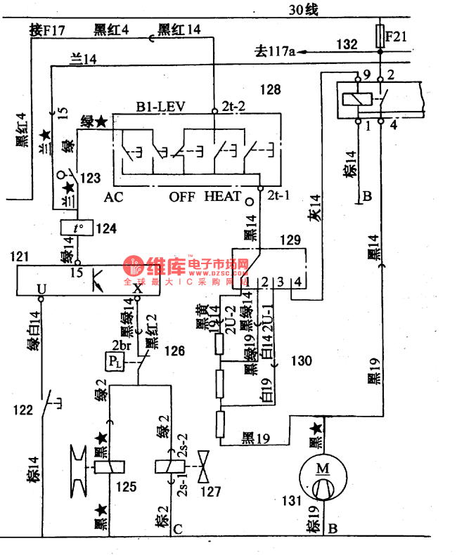
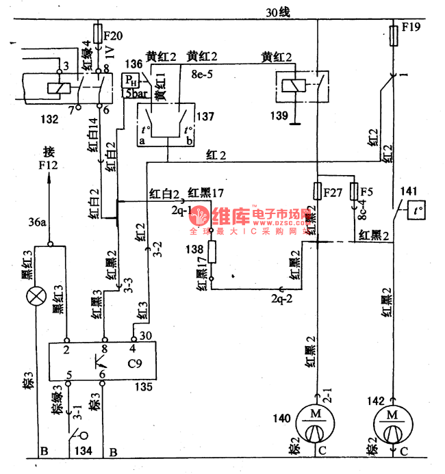
Figure 1 Schematic diagram of Santana 2000 (gasoline injection engine) car air conditioning circuit
36a a light switch lighting; 121 an overload relay; 122 an overload relay to close; 123 a micro switch;
124 a thermostat; 125 an air conditioner compressor electromagnetic clutch; 126 a low pressure switch (2bar); 127 an idle speed corrector solenoid valve:
128-air conditioning (H, V, A, C) control switch; 129 a warm air shift switch (fourth gear); 130 a ventilation system air wither resistance;
131 an air conditioning heater blower; 132 an air conditioning relay

The air conditioning system on the circuit diagram has five key switches, which have a certain interlocking relationship (guaranteed by the mechanical linkage mechanism).
"OFF" button, press the button to open the rest of the keys, otherwise when the rest of the keys have a press (when turned on), the OFF button turns the circuit on.
"AC" button, if you do not press this button, the air conditioner compressor 125 will not work, that is, stop cooling. Press this button, the outside air can enter the cabin for external circulation during normal air conditioning. No fresh air in the room can be discharged outside the car.
"HEAT" button, press this button to heat up quickly. At this time, the refrigeration system often stops working and sends warm air to the car.
The "Bl-LEV" button, double-layer, warm air and cold air are blown out from the blower air duct and the central air outlet door at the same flow rate according to the specified route, and a small amount of air is blown on the windshield glass.
Some damper control lever symbols are:
MAX is the coldest, inner circulation, accelerating cooling, the outside air does not enter the car, and the internal air is not exhausted outside the car.
"VENT" is ventilated, not cooled or heated.
"HEATE A blows the feet and heats up.
"DEF" always winds the windshield and defrosts.
Table 3 illustrates the relationship between the function and the various devices at different lever positions. 
When the temperature is below 5 °C, generally do not need cooling and simply use warm air. At this time, just press the heating (HEAT) button or the defrost (DEF) button to rotate the blower 131. The rotation speed can reach 1500-2500r. /min. Controlled by switch 129 (4th gear) or 119, when switch 129 is pulled to the 4th gear, the current of blower 131 is drawn from the contact of air conditioner relay 132 to reach the maximum speed.
If you want to use air conditioning and cooling, you must press the AC button of the air conditioner switch 128. At this time, the battery current can pass through the micro switch 123, the thermostat 124 and the overload relay 121, the low voltage protection switch 126, and the electromagnetic clutch 125 of the compressor and the idle speed are improved. The solenoid valve 127 is put into work.
The thermostat 124 is equivalent to an evaporator anti-frost switch that controls the compressor to operate within a given range of evaporating temperatures to prevent frosting of the evaporator. The thermostat cuts off the temperature -1.5-+1.5; the on-temperature +1.5-+4.5T. When the evaporator temperature drops to around OT, the thermostat turns the compressor electromagnetic clutch 125 on and off at a frequency of three times per minute.
The low-voltage protection switch 126 is installed at the outlet of the evaporator. When the refrigerant leaks or the low-pressure pipeline is blocked, the compressor will be vacuumed or burnt without oil. To prevent such accidents, the switch 126 is cut off and the cutting pressure is 0.08-0.1lMPa. The switching pressure is 0.23-0.2 gMPa.
The high pressure adjustment switch 136 is mounted on the control circuits of the fan motors 140 and 142 inside the cooling radiator and the air conditioner condenser. When the temperature of the coolant reaches above 95C, the temperature control switch 141 is turned on, that is, the automatic investment is performed. If the water temperature does not exceed this limit, the fan motors 140, 142 are controlled by the air temperature switch 137 and the air conditioner relay 132 of the air conditioning system. Only after the AC button of the air conditioner switch 128 is pressed, the air conditioner relay 132 can pick up the contacts, and the resistors 138 are energized, and the fan motors 140, 142 operate at a low speed.
If the refrigerant pressure in the condenser is too high due to the high temperature, reaching 1.31.1.75 MPa, the high voltage switch 136 is turned on, and the contacts of the relay 139 are sucked, the fan motors 140, 142 will rotate at the same time at high speed, even if the temperature is high. The control switch 141 can also work when it is closed.
The cooling system thermal switch 137 can also operate the relay 139 under the action of temperature to operate the two fan motors.
The function of the fan slow-motion relay 135: If the temperature of the engine and the air-withering system is high after the car is turned off, it is necessary to continue to rotate the fan motor to dissipate heat. At this time, the line 19 is called through the F19 fuse and the red 2 line and the red 3 line. Then, after the fan easing relay and red black 3, red black 2, and resistor 138, the two fan motors are operated at a low speed for a period of time and then stopped.
Electric Test Pen ,Battery Detector,Circuit Tester,Voltage Test Pen
YINTE TOOLS (NINGBO) CO., LTD , https://www.yinte-tools.com