By analyzing the working principle of the PWM device in the SKJ-II digital follower system, the model formula is established and the theoretical transfer function relationship is derived. According to the model formula, the theoretical transfer function of the PWM device is obtained. The correctness of the theoretical transfer function is verified by experiments. It is pointed out that the power supply voltage in the model needs to consider the tube voltage drop of the switch. The modeling of the control system using PWM technology for power conversion has theoretical guiding significance.
1 IntroductionAt present, the DC PWM speed control system is widely used due to its high switching frequency, stable operation at low speed, and excellent dynamic performance, especially in medium and small capacity high dynamic performance systems.
PWM control and converter (referred to as PWM device) is an important component of DC pulse width control system. For the mathematical model of PWM device, only the final approximation transfer function is given in the literature, and the process of block diagram transformation is not explained. And parameter analysis. The SKJ-II digital servo system contains a speed control loop, which includes the PWM device. Based on the PWM device model used in the system, the extended analysis is performed to obtain the derivation and transformation process of the model, which provides the necessary PWM device model. The theoretical basis.
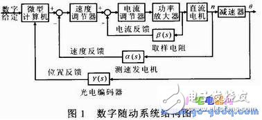
2 Model building and block diagram analysisThe structure of the SKJ-II digital servo system is shown in Figure 1. The power amplifier link functions as a PWM controller and a PWM converter.

In order to facilitate the research, the power amplifier part is divided into two steps, which are respectively referred to as PWM controller and H-bridge, UX11(s) signal is used as the input of PWM device, Ud(s) is the output of PWM device, Ï(s) is Intermediate amount.
2.1 Static analysis
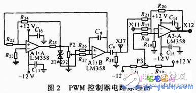
The circuit that implements the PWM controller is shown in Figure 2. The model of the PWM device is pre-established, and its input signal is first determined. The input signal is UX11 (X11 input signal), which is determined by the output of the current regulator at the front end of the system. In the figure, the XJ7 terminal is the output end of the triangular wave generating circuit, the operational amplifier A1:A in the triangular wave generating circuit constitutes the adder, the operational amplifier A1:B constitutes the reverse integrator, and the potentiometer P2 is mainly used to control the frequency of the generated triangular wave. 2DW232 is a bidirectional Zener diode that acts as a limiting resistor. The operational amplifier A3:A and the peripheral resistor constitute an inverting summing amplifier circuit. Because of the large amplification factor, the linear signal is amplified when the signal is small, and the large signal is operated in the nonlinear saturation state.

Perfume Lotus Tea Perfume Lotus TeaPerfume test
YIWU BEAUTYPLUS ART NAIL CO., LTD. , https://www.cn-gangdao.com