Compared with Iron Man, the heart is driven by the core
How do you take off?
Learn driving knowledge
You are hero
â€Common MOS tube driving methods include non-isolated direct drive, bootstrap drive, and isolated transformer drive and optocoupler isolation drive. In the commonly used switching power supply topology, such as Buck, full bridge, half bridge, etc., NMOS is used as the switch tube, and some of the S ends of the tube are not grounded, and the potential changes with the conduction state of the MOS tube, and the MOS tube is driven. The gate signal is based on the potential of the S terminal, and the turn-on voltage of the MOS transistor is about 4.5V. In order to ensure that the tube is completely opened, the driving voltage is generally greater than 10V, and it is appropriate to take about 12-15V. Therefore, to ensure that the MOS transistor can work normally, the G-pole voltage should change with the potential of the S-side, and the voltage between the GS should reach a stable 12V.
If direct drive mode is used, the level is based on the ground of the circuit. When the potential of the S terminal rises, the potential of the G terminal does not change, and the MOS transistor cannot work normally. At this time, a capacitor can be selected, and the negative terminal is connected to the S terminal, and the positive terminal is connected. Keep a 12V stable power supply, and charge the G terminal through this capacitor, you can achieve a stable 12V voltage at the GS terminal. This is like a water level. The capacitor is a water tank. It floats on the river. The potential of the S terminal is like the water level of the river. The ground of the circuit is better than the sea level. Generally, the sea level is used as the reference. The water level of the river will change with the weather, and the water tank will change. The water level does not change the water level difference between the river and the river. This kind of driving method is called bootstrap driving. The capacitor for storing energy is called bootstrap capacitor, and the potential of S terminal can be called “suspended groundâ€. As shown in Figure 1 below, C5 is the bootstrap capacitor, which is usually between a few uF and 100uF.
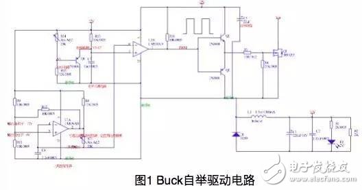
But the circuit shown in Figure 1 is incomplete, powering the front drive through the bootstrap capacitor, but who is charging the bootstrap capacitor? Assuming that the circuit works normally, only two positions are relatively stable. One is the input voltage of 30V and the other is an output voltage of 12V. If the input power supply is used for a long time, there is a voltage difference of 18V (30-12). If the current limiting resistor is large, 30V passes through the current limiting resistor to charge the capacitor slowly, and the current is not enough to start the driving part; the current limiting resistor is selected to be small. The loss is large, and the output voltage of 12V is consistent with the voltage required by the bootstrap capacitor, and when the circuit is working normally, it can provide a large charging current to maintain the bootstrap capacitor voltage stable.
Can the output voltage be directly connected to the bootstrap capacitor? The answer is no, the circuit is working. When the MOS transistor is turned off, due to the clamping action of the diode, the potential of the S terminal is -0.7V, then the potential of the G terminal is less than or equal to 11.3V, so that the output can charge the bootstrap capacitor. When the MOS is turned on, the potential of the S terminal is approximately 30V. At this time, the potential of the G terminal is greater than the output voltage. If it is directly connected, the bootstrap capacitor will charge the output and will be discharged soon, resulting in the failure to start the drive in the next cycle. It is not allowed, so the charging has a direction, here you need to connect a fast recovery diode.
Then analyze the working process of the circuit: When the power supply is powered on, it will find that the circuit can't be started, because the bootstrap capacitor has no voltage, there is no output without driving, so you need to input the power supply to charge the bootstrap capacitor first when charging, when charging to 12V Then power the front drive circuit. Since there is a voltage difference of 18V, in order to reduce the loss, a current limiting resistor of about 20k can be selected here, so that the small current of the bootstrap capacitor is about 1mA is slowly charged. Another advantage of this is that the soft start of the circuit is realized. , reduce stress. However, the charging current is only 1 mA. There is a triangular wave generator, a level-adjustable circuit, and a driving circuit. The current required for the driving circuit is at least tens of mA. The direct charging will find that the bootstrap capacitor is always full. Because the charging current is not enough, you can design this. A switch, when the first power-on, the 30V input power supply charges the bootstrap capacitor with a current of 1mA. At this time, the switch is turned off and does not supply power to the rear circuit. When the voltage of the bootstrap capacitor is charged to 12V, the switch is turned on. The bootstrap capacitor supplies power to the drive, so that the circuit has a certain output, and the output voltage adds energy to the bootstrap capacitor in time to make it work normally. Therefore, the purpose of this switch is to charge the capacitor to 12V for the first time, and then it will remain in the open state.
Along this line of thought, the switch tube is first selected. Since it is connected to the power supply terminal, the P tube is selected here. To charge to about 12V, you can select an 11V voltage regulator diode string between b and ground. In order to limit the current, add a current limiting resistor. However, due to the presence of this Zener diode, when the voltage of the bootstrap capacitor is slightly reduced, for example, to 11V, the switch is turned off, and the output voltage rises to 12V, which takes a while, and does not reach higher than the bootstrap capacitor. At the potential, the bootstrap capacitor cannot be charged and the circuit cannot continue to operate. The key to this is the 11V Zener diode. If the diode is short-circuited when the switch is turned on, then this problem can be solved. Therefore, a switch is needed here, and it is shorted to the ground, and the N tube is selected. as shown in picture 2. In the figure, Q5 is PNP, Q4 is NPN, power on is on, Q5 is off, 30V is charged to C5 through R5, charged to 12V, Q5 is on, then its collector potential reaches 11.3V, use this potential to drive Q4 is turned on, so that Q4 can be short-circuited to D4, so that even if the bootstrap capacitor is reduced to 6V, Q5 can be turned on, and the output current continues to maintain the driving circuit, thus driving the entire circuit.
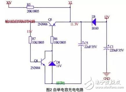
Figure 2 bootstrap capacitor charging circuit
At this point, the bootstrap driver circuit portion of the Buck circuit is designed. Bootstrap drivers are widely used in many places due to their simple circuit, especially in Buck and bridge circuits. However, in the actual design, from the perspective of the simplicity and reliability of the circuit, it is more important to choose an integrated chip. There are also a lot of integrated chips, such as IR's IR21XX series, commonly used IR2104, IR2110, and TI's, as shown in Figure 3 below.

The picture shows 3 TI's bootstrap driver chip part model
According to the data sheet, select the appropriate integrated chip to complete the circuit design.

After learning, I feel that my knowledge power is going to heaven.
Crystal Clear Back Sticker,Phone Sticker,Mobile Phone Back Skin,Crystal Clear Phone Skin
Shenzhen Jianjiantong Technology Co., Ltd. , https://www.jjthydrogelprotector.com