In the development of industry, fieldbus plays a very important role, mainly used in petroleum, chemical, power, medicine, metallurgy, processing and manufacturing, transportation, defense, aerospace, agriculture and buildings and other fields.
Today Xiao Bian gave you a brief introduction of modbus communication protocol, profibus, FF, CAN bus and several other field buses.
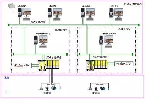
Modbus communication protocol
The Origin and Development of Modbus
Modbus was invented by Modicon (now a brand of Schneider Electric) in 1979 and is the world's first bus protocol that is truly used in industrial sites.
In order to better popularize and promote the distributed application of Modbus on Ethernet, Schneider has transferred ownership of the Modbus protocol to the IDA (Interface for Distributed Automation) organization and established the Modbus-IDA organization. It laid the foundation for the future development of Modbus. In China, Modbus has become the national standard GB/T19582-2008. According to incomplete statistics: As of 2007, the number of Modbus node installations has exceeded 10 million.
In order to better popularize and promote the distributed application of Modbus on Ethernet, Schneider has transferred ownership of the Modbus protocol to the IDA (Interface for Distributed Automation) organization and established the Modbus-IDA organization. It laid the foundation for the future development of Modbus. In China, Modbus has become the national standard GB/T19582-2008. According to incomplete statistics: As of 2007, the number of Modbus node installations has exceeded 10 million.
Application of Modbus
A common language used in electronic controllers. Through this protocol, controllers can communicate with each other, controllers via a network (such as Ethernet), and other devices.
When communicating over the same Modbus network, this protocol determines that each controller needs to know their device address, identify messages sent by address, and decide what action to take.
This protocol supports legacy RS-232, RS-422, RS-485, and Ethernet devices. Many industrial devices, including PLCs, DCS, smart meters, etc. are all in use.

Modbus features
Standard, open, users can use the Modbus protocol free of charge, without the need to pay licensing fees, it will not infringe intellectual property rights. Currently, there are more than 400 manufacturers that support Modbus and more than 600 products that support Modbus.
Modbus can support a variety of electrical interfaces, such as RS-232, RS-485, etc., and can also be transmitted on various media, such as twisted pair, fiber, and wireless.
The Modbus frame format is simple, compact and easy to understand. Users are easy to use, and vendor development is simple.
FF field bus
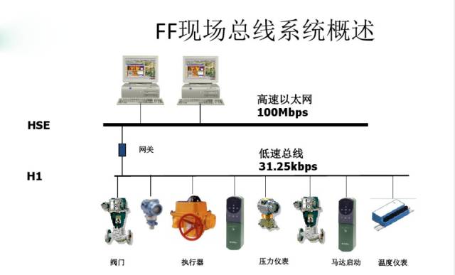
What is FF Fieldbus?
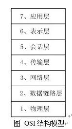
Foundation Fieldbus, FoudationFieldbus, abbreviated FF. It is based on the ISO/OSI open system interconnection model, taking the physical layer, data link layer, and application layer as the corresponding layers of the FF communication model, and adds a user layer at the application layer.
FF Fieldbus Features
The FOUNDATION fieldbus is divided into two communication rates: low-speed H1 and high-speed H2. H1's transmission rate is 3125Kbps, communication distance up to 1900m (can be extended with repeater), can support bus power supply, support intrinsically safe explosion-proof environment. The transmission rate of H2 is 1Mbps and 2.5Mbps, and the communication distance is 750m and 500m.
The physical transmission medium can support twisted pair, fiber optic cable and wireless transmission. The protocol conforms to the IEC1158-2 standard. The physical medium's transmission signal is encoded in Manchester. The center position of each transmitted data is either positive or negative. The positive transition represents 0 and the negative transition represents 1, so that the serial data bitstream has sufficient positioning information to keep the time synchronization of the sending parties. The receiver can judge the “1†and “0†state of the data according to the polarity of the transition, and can also accurately locate the data according to the center position of the data.
PROFIBUS
The origin of PROFIBUS
PROFIBUS is the abbreviation of Process Field Bus. Profibus is the national industrial fieldbus protocol standard developed by Federal Republic of Germany in the early 1990s. It is codenamed DIN19245, which consists of 13 industrial companies and five institutes after more than two years. Time is done.
In 1996, it was approved by the European Electrotechnical Commission as a European standard EN50170. According to the European Standardization Regulations, EN50170 was automatically legally recognized by all European national standardization bodies in the year. Germany canceled the original PROFIBUS national standard DIN19245 and replaced it with EN50170.
From now on, all open tenders in Europe are conducted on the basis of EN50170. EN50170 provides manufacturers and users with the highest standards in protecting investment. PROFIBUS offers a transparent network from the sensor up to the management level. Because of this, PROFIBUS can be applied in many ways, from the automotive industry, machine manufacturing, food industry, transportation, and environmental engineering.
PROFIBUS features
The maximum transmission message length is 255B, the maximum data length is 244B, and the typical length is 120B.
The network topology is a line, tree, or bus type with active bus termination resistors at both ends.
The transmission rate depends on the network topology and bus length, ranging from 9.6 Kb/s to 12 Mb/s.
The number of sites depends on the signal characteristics. For example, for shielded twisted pairs, each segment has 32 stations (without transponders) and up to 127 stations with transponders.
The transmission medium is shielded/unshielded twisted pair or optical fiber.
When twisted pairs are used, the transmission distance can be up to 9.6 km. When using optical fibers, the maximum transmission length is 90 km.
The transmission technologies are RS-485 transmission of DP and FMS, IEC1158-2 transmission of PA, and optical fiber transmission.
A single bus orientation protocol is used, including token transfer between master stations and master-slave mode between slave stations.
Data transmission services include both cyclic and non-cyclical types.
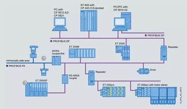
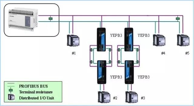
Application of PROFIBUS
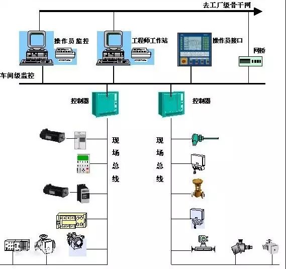
Field device layer
The main function is to connect field devices, such as distributed I/O, sensors, drivers, actuators, and switch lights, to complete field device control and chain control between devices. The master station is responsible for bus communication management and communication of all slave stations.
Workshop monitoring layer
For example, the connection between the main controllers of three production lines in a workshop completes plant level equipment monitoring. Workshop level monitoring includes on-line monitoring of production equipment status, equipment failure alarms, and maintenance. Usually there are plant-level production management functions such as production statistics, production scheduling, and so on. Workshop level monitoring usually requires the establishment of a workshop monitoring room on operator workstations and printing equipment. The plant-level monitoring network can use Profibus-FMS, which is a multi-master network. At this level, the data transmission speed is not the most important, but it must be able to transmit large-capacity information.
Factory management
Workshop operator workstations can be connected to the shop office management network through a hub to send shop floor production data to shop floor management. As a subnet of the main network, the workshop management network is connected to the plant backbone network through switches, bridges or routers, and integrates shop floor data into plant management.
CAN bus
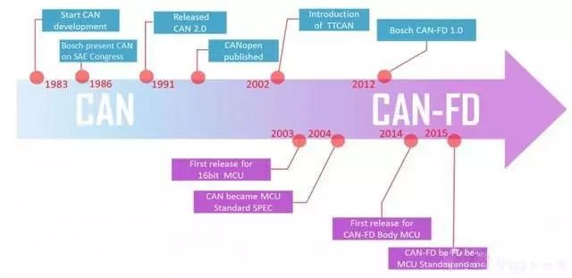
The origin of CAN bus
CAN was developed by Germany's BOSCH and several semiconductor integrated circuit manufacturers. It was originally designed specifically for the automotive industry. It is used for data communication between automotive internal measurement and execution components. Currently, it has been widely used in discrete applications, and It has been approved by the ISO/TC22 Technical Committee as an international standard IS011898 (communication speed 1 Mbps) and IS011519 (communication speed 1251cbps).
CAN bus technology features
The communication transmission medium adopted is twisted pair, and the communication speed can be up to 1 Mbps/40m, and the direct transmission distance can be up to 10km/50kbps. Up to 110 devices can be hooked up.
The signal transmission of CAN adopts the short frame structure, the longest number of effective bytes of each frame is 8, so the transmission time is short, the probability of being interfered is low.
CAN supports multi-master operation. Any node on the network can actively send information to other nodes at any time, supporting point-to-point, point-to-multipoint, and global broadcast methods for receiving/sending data. It adopts bus arbitration technology. When several nodes transmit information on the network at the same time, the node with higher priority can continue to send data, while the node with lower priority stops sending actively, thus avoiding bus conflicts.
CAN bus application
CAN bus in the field of industrial control mainly uses low-speed fault-tolerant CAN, that is ISO11898-3 standard, and 500 Kbps high-speed CAN is often used in the automotive field.

A certain imported vehicle owns multiple control networks such as body, comfort, and multimedia. Among them, the body control uses CAN network, the comfortable use of LIN network, the multimedia use of MOST network, the CAN network as the main network, and the control of engine, transmission, ABS, and other body safety. Modules, and share the speed, speed, oil temperature, etc. to the entire vehicle, to achieve intelligent control of the car, such as automatically locking the door at high speed, when the airbag pops up, automatically open the door and other functions.
CAN system is divided into high-speed and low-speed, high-speed CAN system uses hard-line is a power type, speed: 500kbps, control ECU, ABS, etc.; low-speed CAN is comfortable, speed: 125Kbps, the main control instrument, security and so on.
1.0mm (.039") Female Headers
Overview
Whenever there is a need for fitting small-sized connectors in compact devices, the 1.0mm pitch female header, or sometimes referred to as header connector, is ideally suited for this application. Not only does this female header space-savvy, but it is also designed for vacuum pick and place that makes it suitable for high volume automated manufacturing.Antenk offers these low profile, easy-install, SMT or THM miniature female connector plugs at high quality and affordable China-quoted price, for board-to-board connection, snuggly fitting the pins of a male header and acting as a receptacle.
Assembly and service is simple with either vertical (straight), elevated or at a right angle configuration/orientation, which can dissipate current of about 1.0 A or less in a tape and reel packaging. The filleted corners can also remove shadowing allowing optimization of LED output.
Also, the 1.0mm pitch female headers are made to work in Arduino boards, Arduino Pro and Arduino Mega with either single or double-row female headers, facilitating connections for programming and incorporation into other circuits. They have the perfect height for clearing the USB-B connector and great for stacking multiple shields.
Female header always called as [Header connector", Antenk provide widely range of header connector, from 2.54mm (.100″ inch) pitch to 1.0mm (.039″ inch) pitch. The number of pins (contacts) is from 2 to 40 pins per orw. There are three type: Straight (Dip Vertical), Right angle, SMT (surface mount).
If you can not find the items you interest from above items, welcome to contact us, and you will always get fully responsive from us.
Applications of 1.0mm Pitch Female Headers
Its small size is most suitable for PCB connections of small equipment and devices such as:
Arduino Boards
Architectural and sign lighting
Retail and display lighting
Fluorescent LED retrofit lighting
Cabinet or furniture lighting
Commercial / residential cove lighting
WiFi equipment
Gaming consoles,
Measurement instruments
Medical Diagnostic and Monitoring equipment
Communications: Telecoms and Datacoms
Industrial and Automotive Control and Test
Mount Type: Through-hole vs Surface Mount
At one side of this female header is a series of pins which can either be mounted and soldered directly onto the surface of the PCB (SMT) or placed into drilled holes on the PCB (THM).
Best used for high-reliability products that require stronger connections between layers.
Aerospace and military products are most likely to require this type of mounting as these products experience extreme accelerations, collisions, or high temperatures.
Useful in test and prototyping applications that sometimes require manual adjustments and replacements.
1.0mm vertical single row female header, 1.0mm vertical dual row female header, 1.0mm Elevated single row female header, 1.0mm Elevated dual row female Header, 1.0mm right-angle single row female header and 1.0mm right-angle dual row female header are some examples of Antenk products with through-hole mount type.
Surface-Mount
The most common electronic hardware requirements are SMT.
Essential in PCB design and manufacturing, having improved the quality and performance of PCBs overall.
Cost of processing and handling is reduced.
SMT components can be mounted on both side of the board.
Ability to fit a high number of small components on a PCB has allowed for much denser, higher performing, and smaller PCBs.
1.0mm Right-angle Dual Row female header, 1.0mm SMT Single row female header, 1.0mm SMT Dual row female header and 1.0mm Elevated Dual Row female Header are Antenk`s SMT female headers.
Soldering Temperature for 1.0mm Pitch Female Headers
Soldering SMT female connectors can be done at a maximum peak temperature of 260°C for maximum 60 seconds.
Orientation/Pin-Type: Vertical (Straight) and Right-Angle
1.0mm pitch female headers may be further classified into pin orientation as well, such as vertical or straight male header or right-angle female header.
Vertical or Straight Female Header Orientation
One side of the series of pins is connected to PCB board in which the pins can be at a right-angle to the PCB surface (usually called "straight" or [vertical") or.
Right-Angle Female Header Orientation
Parallel to the board's surface (referred to as "right-angle" pins).
Each of these pin-types have different applications that fit with their specific configuration.
PCB Connector Stacking
Profile Above PCB
This type of configuration is the most common way of connecting board-to-board by a connector. First, the stacking height is calculated from one board to another and measured from the printed circuit board face to its highest insulator point above the PCB.
Elevated Sockets/Female Headers
Elevated Sockets aka Stacked sockets/receptacles or Mezzanine are simply stacked female headers providing an exact distance requirement between PCBs that optimizes electrical reliability and performance between PCB boards.
Choosing this type of stacking configuration promotes the following benefits:
Connector Isolation - the contacts are shrouded preventing cable connection mishaps and good guidance for the mating header connectors.
For off-the-shelf wireless PCB module, stacking height is optimized with elevated sockets.
Offers superior strength and rigidity.
Polarisation prevents users from inverted insertion.
Single, Dual or Multiple Number of Rows
For a 1.0mm straight or vertical female header, the standard number of rows that Antenk offers ranges from 1 to 2 rows. However, customization can be available if 3 ,4 or n number of rows is needed by the customer. Also, the number of contacts for the single row is about 2-40 pins while for dual row, the number contacts may vary from 2-80 pins.
Pin Material
The pins of the connector attached to the board have been designed with copper alloy. With customer`s demand the pins can be made gold plated.
Custom 1.0mm Pitch Female Headers
Customizable 1.0 mm pitch female headers are also available, making your manufacturing process way faster as the pins are already inserted in the headers, insulator height is made at the right size and the accurate pin length you require is followed.
Parts are made using semi-automated manufacturing processes that ensure both precision and delicacy in handling the headers before packaging on tape and reel.
Tape and Reel Packaging for SMT Components
Antenk's SMT headers are offered with customizable mating pin lengths, in which each series has multiple number of of circuits, summing up to a thousand individual part number combinations per connector series.
The tape and reel carrier strip ensures that the headers are packaged within accurately sized cavities for its height, width and depth, securing the headers from the environment and maintaining consistent position during transportation.
Antenk also offer a range of custom Tape and reel carrier strip packaging cavities.
Pcb Header,1.0Mm Female Pin Header,1.0Mm Female Header Connector,1.0Mm Pcb Header,0.039" Female Headers,0.039" Pin Header, 1.0mm Female Pin Header SMT, 1.0mm Female Pin Header THT
ShenZhen Antenk Electronics Co,Ltd , https://www.antenkcon.com