At present, switching power supplies are widely used in various terminal devices and communication devices based on electronic computers, which are small, lightweight and highly efficient. They are an indispensable power supply method for the rapid development of electronic information industry. Correspondingly, driven by the development of microelectronics technology, the development of DSP chips is changing with each passing day, the functions are increasingly powerful, the cost performance is rising, the development methods are continuously improved, and the processing speed is 10 to 15 times faster than the CPU. Therefore, the switching power supply based on DSP chips It can be said that it is a natural guarantee, has a broad prospect, can be used in the selected on-board power supply, is also the future development trend of switching power supply.
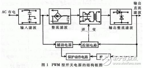
The structural block diagram of the PWM type switching power supply is shown in Figure 1.
After the mains signal is input filtered and rectified and filtered, the AC/DC conversion is realized, and the AC power of the grid is directly rectified into a smoother DC power for the next level of conversion; after the inverter, the DC/AC conversion is realized, and the rectified DC power becomes AC, which is the core part of PWM control power supply PWM control. The higher the frequency, the smaller the ratio of volume, weight and output power. Finally, through output rectification and filtering, it provides stable and reliable according to load requirements. DC power supply.
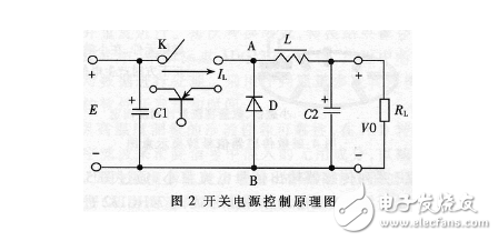
The schematic diagram of the switching power supply control is shown in Fig. 2. In the figure, the switch K is repeatedly turned on and off at a certain time interval. When the switch K is turned on, the input power source E can be supplied to the load RL through the switch K and the filter circuit. To provide energy for the load; in order to obtain continuous energy from the load, the switching regulator must have a set of energy storage devices to store some of the capacity when the switch is turned on, and release it to the load when the switch is turned off [4]. In Figure 2, the inductor L and the capacitor C2 are used to store energy. When the switch is turned off, the energy stored in the inductors L and C2 is released to the load through the diode D, so that the load obtains continuous and stable energy. The load current is continuous, so it is called the freewheeling diode. The average voltage EAB between AB can be expressed as:
EAB=TON|T&TImes;E (1)
Where TON is the time each time the switch is turned on, and T is the duty cycle of the switch on and off (ie, the sum of the switch pull-on time TON and the off-time TOFF).
Equation (1) shows that the ratio of the switch-on time to the duty cycle changes, and the average value of the voltage between the ABs also changes. Therefore, as the load and the input power supply voltage change automatically, the ratio of TON to T is automatically adjusted. The output voltage V0 remains unchanged. Changing the on-time TON and the duty cycle ratio also changes the duty cycle of the pulse. This method is “Time Ratio Control†(TIme RaTIo Control, abbreviated as TRC) [1]. Here, according to TRC The principle selects the switching period T constant, and changes the duty ratio by changing the pulse width TON. This method is called pulse width modulation (PWM), which is used to control the voltage amplitude frequency.
3 DSP chip TMS320LF2407 introductionThe architecture of the TMS320 series DSP is designed for real-time signal processing. This series of DSPs combines real-time processing and control peripheral functions to provide an ideal solution for implementing control systems.
The TMS320LF2407 has the following features based on the TMS320 series [2]:
(a) The high-performance 10-bit analog-to-digital converter (ADC) has a conversion time of 500ns and provides up to 16 analog inputs.
(b) The CPU core based on the TMS320C2xx Dijon guarantees its code compatibility with the TMS320 family of DSPs.
(c) Two event manager modules EVA and EVB, each providing two 16-bit general-purpose timers and eight 16-bit PWM channels.
(d) Up to 24K FLASH program memory.
(e) Scalable external memory.
(f) Five external interrupts (two drive protection, reset and two upper maskable interrupts).
4.1 Basic Principles of SPWM Control
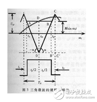
The so-called SPWM or PWM pulse width changes according to the sine law. From the sampling theory: narrow impulses with different impulses and different shapes are added to the link with inertia, the effect is basically the same, in order to get a sine wave at the output, you need to output a A series of rectangular waves with equal amplitudes and different widths. Using the regular sampling method of triangular carriers, a rectangular wave whose width varies according to sinusoidal law can be obtained. As shown in Fig. 3, the midpoint of each pulse is corresponding to a triangular wave. The midpoint is symmetric. At the negative peak of the triangular carrier, TD samples the sine wave to obtain the D point, and the D point makes a horizontal straight line and the triangular wave respectively intersects the A point and the B point. At the time point A, the tA and the B point control the power at the time tB. The continuity of the device. It can be seen that the length of AB is the pulse width. The following relationship can be obtained from the figure:
AB=Tc(1+sinωctD)/2 (2)
According to this relationship, if there are N rectangular waves in one cycle, the duty ratio of the first rectangular wave is:
4.2 Using SMS320LF2407 to achieve SPWM control
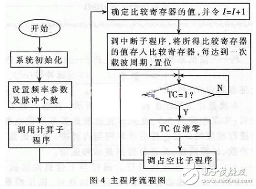
Here, the general timer 3 in EVB and the related comparison unit are taken as an example to illustrate the process of implementing SPWM control.
ALL Kinds of 4G NB Vehicle GPS Tracker, there must be one which should meet your expectation.
ES810-CM the hot-sell with certificates of FCC,CE, PTCRB, Verizon, AT&T,T-Mobile, Sprint.
ES811 the waterproof version of ES810 with certificates of Verizon, Sprint.
ES840 the OBDII with certificates of FCC, Verizon, Sprint.
ES821 the smallest asset GPS Tracker with the certificates of FCC, CE,T ELEC, Verizon, T-Mobile, Sprint.
ES826 the long standby with the certificates of FCC, PTCRB, TELEC, AT&T, Verizon, Sprint.
ES410 the BG95(NB) version of ES810
ES420 the BG95(NB) version of ES821
ES430 the BG95(NB) version of ES826
NB vehicle GPS Trackers,NB car GPS Trackers,Waterproof car GPS Tracker,IP65 car GPS Tracker,OBDII NB vehicle GPS Trackers,Wireless NB GPS Trackers
eSky wireless Inc , https://www.eskygpsiot.com