This white paper provides an overview of the functionality and performance of the Aeroflex SGA analog signal generator, highlighting the technologies on which the leading ultra-low phase noise and switching speed metrics depend, as well as information on the latest additions to avionics test measurement options.
As a compact portable universal analog signal generator, the SGA analog signal generator is only half-rack width, 4U rack unit height, the series offers two models SGA-3 and SGA-6, the frequency range is 100kHz ~ 3 GHz and 100 kHz to 6 GHz. The high performance of its hardware specifications is directly aimed at R&D lab applications. The frequency and level switching speeds are suitable for high-speed switching requirements in manufacturing test systems, such as RFIC, and offer a more economical purchase price.
The main optional features of this series include high RF power output, analog modulation (AM/FM/PM), pulse modulation and avionics.
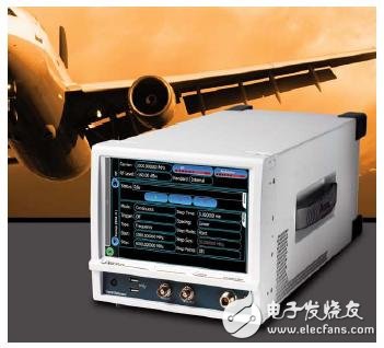
Figure 1: Aeroflex SGA RF signal generator provides fast settling time and low phase noise with new avionics measurement options
Phase noise and speed
The SGA's excellent phase noise characteristics and low distortion signal levels make it possible to handle the widest and most rigorous measurements of modern receivers and RF communication systems. Receiver selectivity over 80dB dynamic range can still be achieved with typical SSB phase noise performance of -135 dBc/Hz (carrier frequency 1 GHz, frequency offset 20 kHz). Combined with this ultra-low phase noise performance and simultaneous implementation is an ultra-fast frequency synthesizer and the same fast RF level control loop that enables carrier frequency or RF levels in 100 μs (list mode) or 5 ms Establish and implement arbitrary switching within (traditional mode). These parameters ensure maximum throughput in semiconductor production trials such as RFIC and frequency hopping applications such as FM radio.
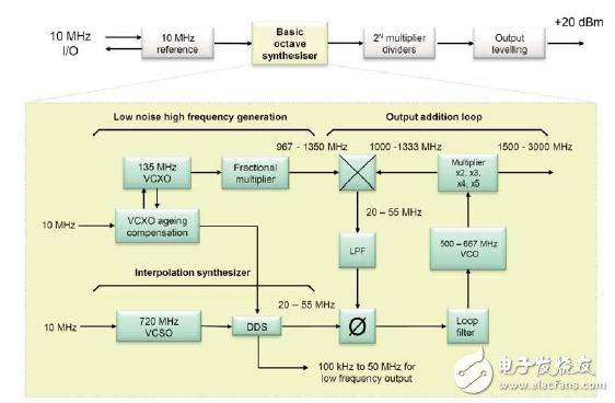
Figure 2: Block diagram of the SGA ultra-high speed, low phase noise synthesizer
The low phase noise performance shown in Figure 3 is achieved using the multi-loop synthesizer shown in Figure 2. A low-noise “reference†phase-locked loop (PLL) uses a low-noise crystal oscillator running at maximum output (for optimal signal-to-noise ratio) to cause a fractional multiplier to produce a frequency range of 967-1350 MHz (22.5 Signal of MHz step). To interpolate between 22.5 MHz steps, an “interpolated†PLL provides a tuning range of 11.25 MHz (from 22.5 MHz to 33.75 MHz; if wideband FM is to be generated, from 33.75 MHz to 55 MHz to provide additional ±10 MHz swing) oscillator. An "output" loop then adds or subtracts the frequency from the reference and interpolation PLLs, keeping the tuning range of the interpolating oscillator at an absolute minimum.
The above output loop consists of a VCO whose frequency is doubled to 1000-1333 MHz. Mix the signal with a low noise reference signal. Phase comparison of the difference frequency and the interpolated signal, low pass filtering the phase detector output before controlling the VCO to complete the loop.
Achieving such a fast setup time uses a low noise DA converter to pre-control the VCO and the voltage-tuned varactor bandpass filter. The PLL and output loop in the fractional multiplier use a mixer-based phase detector with a low noise floor but a limited capture range, so the pre-control places the VCO in the desired region. Precision tuning is achieved using a digital discriminator. An FPGA compares the frequencies of the two signals at the phase detector position and adjusts the pre-control voltage to bring the VCO closer to the correct frequency. This causes the VCO to enter the PLL's capture range, which is locked within this range and quickly established to within 0.1 ppm within 100 μs.
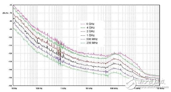
Figure 3: Typical phase noise curves for this series
RF level
The RF output with a standard configuration of +13 dBm maximum can be set to a resolution of 0.01 dB. The maximum calibrated RF level can be increased to +20dBm using the high power option. There is much more to the RF level control that is not covered in the product literature. The S-Series also pays special attention to ensuring that the quality of RF performance exceeds the specification requirements. The main features are:
• The series does not generate positive RF level transients during any frequency or level change during use. This feature is especially important when testing RF components such as power amplifiers because of any excessive positive level transitions or sudden changes. The hair may cause damage or damage to the device under test.
• The source output port VSWR is controlled and further reduces unwanted reflected signals to help ensure that the specified RF level accuracy is achieved when load matching is not ideal. This is common in automated test systems where the cables and switches are located Between the signal generator and the DUT.
• The RF output port ensures monotonicity (single direction). Monotonicity is a measure of the ability of an RF level to have no RF output changes in the opposite direction of the destination direction with a fine RF level step or step. This can significantly reduce the error margin of the receiver sensitivity measurement, which makes the SGA more suitable for test applications in contemporary large dynamic range receivers.
• Very ideal repeatability to ensure the same RF level is produced each time.
A stable RF level can be quickly established in 100 μs by using an output attenuator that can be set to a maximum of 132 dB in 0.25 dB increments. This means that ALC is only required if the RF level adjustment increment exceeds 0.25 dB. The DC voltage of the detected RF output is fed into an ADC that is read by the FPGA. Within the FPGA, calibration data is applied and a digital output from the FPGA is fed into a DAC that pre-controls the ALC to almost exactly the desired level, and ALC rarely needs to do anything else. Very fast attenuator switches are used in the process.
For the SGA-3, the Reverse Power Protection (RPP) option provides additional protection for the meter's RF output, preventing unintentional application of excess RF or DC power to ensure longer meter life and lower total cost of ownership.
Flexible modulation function
With four internal 10 MHz oscillators and two externally modulated outputs, the SGA offers a wide range of modulation mode options. Single sideband AM, FM or PM (phase modulation) can be implemented using any combination of internal and external sources; double sideband AM and FM (or PM); and double sideband external AM and FM (or PM) modulation modes.
Wide AM and FM bandwidth support broadcast system testing by allowing video signals to modulate carriers with minimal distortion. Broadband FM also supports device testing such as FSK for high-speed data transmission and telemetry using frequency shift keying.
Avionics
Following the Aeroflex Aerospace Industry Standard 2030 Series avionics signal generator, SGA introduced the latest avionics options for avionics testing. This option provides customers with the instrumentation landing system (ILS), VHF omnidirectional radio (VOR), internal waveform generation required to mark beacons, and COM ID Morse code for airport identification. The form of avionics parameters is exactly the same as that described in the International Civil Aviation Organization (ICAO) standards. It is a single instrumentation solution for testing airborne navigation receivers and airport alarm monitors and is a required standard test equipment for all civil and military airports, body and cockpit instrument manufacturers, and military subcontractors.
The avionics test excitation source option is generated using four internal modulators of the SGA signal generator. Avionics testing requires a signal generator with excellent modulation integrity, not to mention a safety-critical industry where accuracy and reliability are critical.
ILS
The ILS directs the aircraft to land on the runway by receiving and processing high precision signals. If the aircraft is too high or too low, or too far to the left or right, the ILS will inform the pilot to ensure that the aircraft remains on the route for a safe landing. The heading beacon (LOC) provides lateral navigation and the glide stage (or glide path) provides vertical navigation. Two transmitters on the ground transmit heading beacon signals in the carrier frequency range of 108.10 MHz - 111.95 MHz, one of which is modulated at 90 Hz and one modulated at 150 Hz. These narrow beams are emitted from two separate but co-located antennas, focusing on each side of the runway. The ILS heading beacon receiver on the aircraft analyzes the modulation depth of the two signals and uses the difference between them to calculate the degree of deviation from the centerline of the runway. The modulation depth difference (DDM) is zero when the aircraft is on the route. DDM can be expressed in the form of a percentage (%) or a modulation index. 1% DDM is equal to 0.001 DDM.
The glide-down (GS) system works similarly, but uses a transmit carrier frequency range of 329.15 - 335 MHz. The system calculates the deviation from the ideal glide stage, and the angle between the glide table and the horizontal plane (ie the ground plane) is about 3°.
The heading beacon also provides an identification function: by periodically transmitting a 1,020 Morse code identification signal to provide an internationally recognized symbol for the airport, telling the pilot that the facility is functioning properly and tuning to the correct ILS.
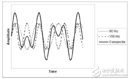
Figure 4: ILS waveform at 0 DDM
It is important to test the accuracy and stability of the signal generator of the ILS system. The size of each audio must be controlled to maintain a constant arithmetic modulation depth (SDM) for each audio. The absolute AM depth accuracy of 90 Hz and 150 Hz audio is important, and the accuracy of the route and the resulting DDM accuracy are also important because it informs the pilot of the information on the aircraft's online route. Figure 4 shows the composite modulation waveform for 0 DDM. In the signal generator, this depends on the AM frequency response of 90 Hz - 150 Hz being as flat as possible, and the amplitude of each modulated signal source is equal.
The relative phase of each audio is fixed by the ICAO standard, and the frequency of each audio results in a composite waveform whose shape repeats at a frequency of 30 Hz.
Generating ILS signals with ID Morse code and/or voice audio requires all four modulation oscillators of the SGA: Oscillator 1 and 2 for 90 Hz and 150 Hz audio, Oscillator 3 for ID audio, and for sound channels Oscillator 4. Amplitude modulation is produced using a portion of the IQ modulator, and its low distortion and high linearity make it ideal for producing accurate and stable modulated signals.
VOR
VOR is used for flight navigation of an aircraft; it indicates the orientation of a fixed beacon (which transmits a VHF composite signal) that is sent to or from the ground. At the same carrier frequency, a second AM audio with a frequency of 9.96 kHz is generated, frequency modulated at 30 Hz with a deviation of ±480 Hz. Comparing the phases of 30 Hz AM audio and 30 Hz FM audio on a 9.96 kHz subcarrier yields aircraft orientation information from the beacon. Figure 5 shows the modulation spectrum of a VOR signal.
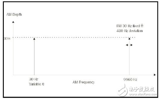
Figure 5: Modulation spectrum of the VOR signal
The position of the aircraft can be derived by using more than one VOR transmitter. The signal also includes the Morse code identifier of the base station and sometimes a sound component.
The relative phase of the signal source determines the azimuth accuracy of the signal generator. This is a key parameter of the VOR system, and the digital generation and control of the modulating oscillator ensures azimuth accuracy better than 0.05 degrees.
Using ID Morse code and/or voice audio to generate a VOR signal requires all four modulation oscillators of the SGA plus an additional non-standard oscillator. Oscillator 1 provides 30 Hz audio for the azimuth signal. Oscillator 2 provides a 9.96 KHz subcarrier, which is the frequency modulated by Oscillator 5 to provide a 480 Hz frequency offset at 30 Hz. Oscillator 3 and 4 provide ID and sound audio as in ILS mode. Figure 6 shows the VOR application screen on the SGA.
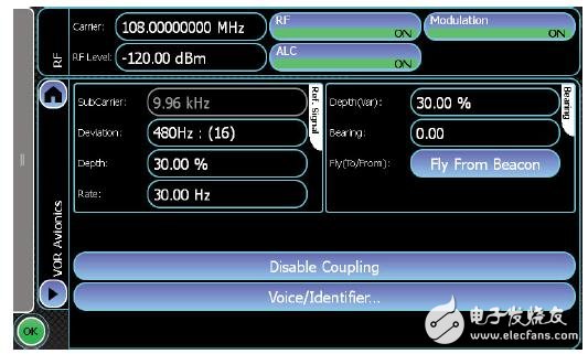
Figure 6: Avionics VOR application screen showing how all information is presented on one screen and how clear touch icons ensure simple and quick setup changes
Sweep/list mode
The full sweep mode provides digital sweep of carrier frequency and RF level in discrete steps. The start, stop, step number (or step) and step time of the step can be set up to a maximum of 65536 steps. Sweep externally triggers sweeps for start, start/stop, and step through the rear panel BNC connector, while up to six glyphs can be used to identify specific events in the sweep. The list mode provides maximum frequency switching speed with a minimum dwell time of 100μs. A table can be created that includes up to 5000 carrier frequencies and RF level values. The start address, stop address, and dwell time can be controlled and externally triggered from a rear panel BNC connector.
Pulse modulation
An optional pulse modulator with an internal pulse generator allows the generation of fast-rising RF signals with on/off ratios that meet the most stringent test requirements for radar RF and IF stages and EMC/ECCM test applications.
Modular instrument concept: "Aerolock" interlock mechanism
The SGA is designed to work with another SGA and a set of S-Series modules installed under it. “Aerolock†is an ingenious, simple and powerful interlocking mechanism that allows an SGA instrument to be combined with a full rack width module or two half rack width modules to form a customized test solution. Figure 7 shows how the two interlocking T-bolts interchange positions to provide a locking mechanism. Each of the two SGAs weighing less than 17 pounds can be easily carried in the lab, factory or outdoors without the need for two people to lift.
When the module is connected to the SGA via a USB plug-and-play interface, the SGA automatically recognizes and runs the module's functions and applications. This supports many applications, including power amplifiers, receiver sensitivity, intermodulation, adjacent channel power testing, and mixer testing, and there are many other applications in the future. Alternatively, one SGA can be combined with the settings of another SGA to allow for fast and simple control over any frequency or range of levels, where two sources with defined relationships are required. Figure 8 shows a combination of two SGAs and a SCO combiner module to form a receiver test system that supports intermodulation distortion, receiver sensitivity, and selectivity testing.

Figure 7: AerolockTM's patented interlocking architecture
General characteristics
The SGA uses a 8.5-inch true color LCD “touch screen†user interface. The newly designed GUI graphical interface displays all relevant setup information on one screen, thus avoiding the need for conventional instruments to be configured from a lower level menu structure. Trouble, all buttons are displayed intuitively in front of the user. Each touch button is large enough to ensure ease of use, even when wearing gloves. You can also connect your mouse and keyboard to improve ease of use when using WindowsTM features.
The SGA does not have a traditional keyboard and buttons, and a large pop-up virtual keyboard appears when the user touches a particular parameter. From the pop-up keyboard, an innovative slider control with adjustable sensitivity (position to the right edge of the display) is enabled to allow the user to adjust specific parameters without looking at the meter. Also from the pop-up keyboard you can also enable a step-up/step-down control that looks a bit like a ruler, where the step size can be set.
The SGA offers up to four USB 2.0 ports (two on the front panel and two on the rear panel), so even with the mouse and keyboard connected, there are still two USB ports available for connection as an S-Series test system. Part of the concept of other S-series instruments. Other uses for the USB interface include updating the instrument's software or connecting a USB power Sensor. The modular structure of the SGA means that repairs can be completed in 30 minutes by module replacement using a calibrated switching module. Fast, "system level" RF adjustments using USB power sensors restore the meter's calibration integrity.
The SCPI format commands can be used to support USB, LAN, and GPIB interfaces when conditions permit. It also supports remote desktop and VNC, allowing remote remote control, and you can even use the iPhone or iPad for any remote control. The GSA includes the remote control emulation capabilities of the 2030 Series and will be extended to include other Effies signal generators and signal generators from other manufacturers.
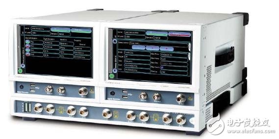
Figure 8: Two SGAs and one SCO combiner
Conclusion
The Aeroflex SGA RF signal generator delivers best-in-class performance through the use of synthesizers based on innovative analog and digital technologies. This provides an ideal platform for dedicated avionics generators to establish industry standards, replacing the Aeroflex 2030 series that has occupied this position for the past two decades. The series will also launch a series of innovative applications to expand the application space of the product.
CCTV Bracket, CCTV Camera Bracket,CCTV Camera Mounts,CCTV Security Camera Mounting Bracket
Chinasky Electronics Co., Ltd. , https://www.chinacctvproducts.com