With the vigorous development of China's economy and the awareness of the protection of land and resources, the state's approval and supervision of land is growing. Moreover, China's power network is becoming stronger and stronger. The 110kV substation, which was originally a backbone network, has now become a terminal station. Its position in the power grid is far less important than before, so the primary wiring form is also segmented by the original single bus or even The main busbar with a single busbar section has a substation with internal bridge wiring.
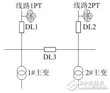
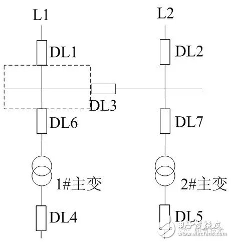
At the same time, from the perspective of saving resources and controlling costs, the new 110kV substation is now in the form of internal bridge wiring, as shown in Figure 1. Compared with the general single-bus segmented wiring method, the inner bridge wiring eliminates the two main transformer high-voltage side incoming circuit breakers and one knife gate.
Figure 1 Traditional inner bridge wiring
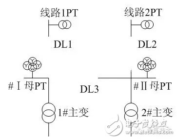
Figure 2 Bridge connection in Danjing Station
1. Design of voltage loop
Since the 110kV Danjing Substation is located in the center of the five-star hotel in Tianfu New District and the “Two Lakes and One Mountain†scenic tourist area, the GIS design of the user is adopted in order not to affect the overall planning of the overall scenic spot and reduce the floor space.
Therefore, when designing the main wiring, two bus bars PT are omitted, and the line single-phase PT is replaced with a three-phase PT, thereby minimizing the floor space, as shown in FIG. 2 .
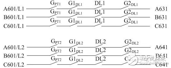
In the review of the map, the voltage secondary circuit design is shown in Figure 3. Obviously, such a design is flawed because the PT knife gate can only react to the line voltage when it is in position, and not necessarily the bus voltage, and can only react to the bus voltage when the switch is running. Moreover, the two busbar voltages do not have a secondary parallel circuit.
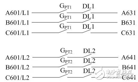
Therefore, the design has been changed, and the bus voltage loop is connected to the switch normally open auxiliary contact, as shown in Figure 4. The improved design corresponds to the actual bus voltage during normal operation.
The two busbar voltages should be juxtaposed by busbar switch DL3 and its two side switches.
Figure 3 voltage loop original
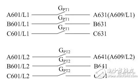
Figure 4 field voltage loop diagram
In actual operation, it was found that the voltage loop design method shown in the figure is still defective. Its defect performance:
One of the line switches (taking DL1 as an example) is in cold standby, the bus-coupled switch DL3 is in the same position, and the other line is operated by the DL3 switch with two main transformers. Since the two busbars are running in parallel at this time, there is no busbar PT on the I mother. Therefore, the protection of the #1 main transformer, the measurement and control voltage, and the metering voltage of the high voltage side of the #1 main transformer can only be obtained by juxtaposition of the secondary side voltage. When the DL1 switch relay protection device is routinely pre-tested, when the whole set of transmission experiments is performed, when the switch manually closes the DL1 switch, the secondary bus voltage A631/B631/C631 will reverse the voltage to the line. This is very dangerous.
The danger is manifested in two aspects:
(1) Reverse power transmission will bring the line to electricity. If the line is overhauled, there will be life casualties;
(2) The line is not overhauled but is charged. If the two voltages are different, a serious power grid accident will occur, which will cause a large-scale power outage. In both cases, the consequences will be serious and will cause incalculable losses.
The solution is as follows:
(1) The operating procedures for the voltage circuit shall be added to the operating procedures of the substation. When the line switch DL1 is in cold standby, all routines of the L1 line PT shall be disconnected for routine testing of the DL1 protection device. Open the next time. This method can indeed solve the problem of secondary voltage reversal when the line switch is cold standby. However, there are new problems when preparing for the operation.
Similarly, the line L1 in the switch DL1 is in the hot standby (the voltage on the line side) is taken as an example, the bus coupler switch is in the DL3 position, and the DL2 switch on the line L2 is operated with the two transformers. At this time, all voltages of the 110 kV voltage level protection, measurement and control, metering, and fault recording are secondary voltages from the #2PT of the ball line L2.
At this time, if the line L2 is tripped to the side switch and the whole station loses power, the standby device should operate correctly because the line is prepared to meet the operating conditions. Firstly, the DL2 sends a jump command from the standby DL2. After the DL2 is indeed in the jump position, the standby device sends a closing command to the switch DL1. When the DL1 is closed, the standby operation is completed, and the entire station resumes the power supply. When the actual joint preparation and self-injection device is running, it is found that after the self-injection action, the protection voltage, measurement and control, and metering voltage of the whole station are normal, but the mother metering voltage loss signal is issued.
Finally, after checking the secondary circuit of the metering voltage, it is found that the metering voltage loop of the I and II mothers has not been changed, or the voltage loop is connected according to the circuit shown in Figure 3, but only after the line knife normally open node is re-moved, and has not passed the switch DL1. DL2 normally open auxiliary contact.
Therefore, after the self-injection switch operation, the I and II mothers are still in parallel operation, and the II mother metering voltage and voltage return to normal. At this time, the #2PT on the line L2 has no pressure on the primary side, and the secondary side reverses the voltage on the primary side. Since the secondary voltage is similar to a step-up transformer when the voltage is reversed to the primary side, a large excitation current is required, and the excitation current exceeds the secondary metering open rating, and then trips.
In addition, the connection method of the metering voltage is routinely tested in the cold standby state of the line switch DL1, and when the two sections of the busbars are operated in parallel, when the circuit breaker DL1 is hand-held, the metering voltage of the I mother still reaches the primary side of the line L1. Reverse power transmission causes the metering switch to trip.
If the measurement and control device does not have the signal to send the I mother metering open trip at this time, when the DL1 resumes operation, the switch DL1 has no metering voltage and cannot be correctly metered, resulting in loss of the metering.
(2) The actual line switch operation is that the circuit breaker is in the position, the knife gates on both sides of the circuit breaker are in position, and the bus voltage is equal to the line voltage. In order to make the first and second consistency, and from a safety point of view, the normally open contacts of the knife gates on both sides of the circuit breaker should be connected in the voltage circuit, as shown in Figure 5. Really realize that the secondary circuit responds correctly with one time and reacts to the normal voltage.
Figure 5 improved voltage loop diagram
It can be seen that in a substation with a three-phase line PT without a bus bar PT, the voltage secondary circuit is much more complicated than the secondary circuit of a single bus segment. The more complex the secondary circuit, the more likely it is to fail and the less reliable it is. This is the risk of simplifying the secondary circuit once.
2. Current loop design
In the design of the current loop, the differential current of the transformer is mainly different from the general single-bus segmented wiring substation. For a typical single-bus substation substation, the differential current of the transformer is the current phasor of each side of the transformer, and the current direction of each side is directed by the busbar of each side switch to the transformer.
In the inner bridge wiring method referred to herein, the high voltage side of the #1 main transformer refers to the bus coupling switch DL3 and the incoming line L1 switch DL1. The high voltage side of the #2 main transformer is the bus coupler switch DL3 and the line switch DL2. When the DL3 current is connected to the #1 main transformer, its current direction should be that the II busbar points to the I-mother direction, and when the #2 main transformer is connected, the current direction should be directed from the I-bus direction to the direction of the II bus, and the two sets of current directions The sex is just the opposite.
In the case of two busbars, the direction of the current should be directed by the busbar to the line to achieve the purpose of protecting the line. When the line switches DL1 and DL2 are respectively used as the high-voltage side of the main transformer, the current connected to the main transformer should be the protection master. The purpose of the transformer is so the direction should be the direction of the line to the bus. The polarity of the current is opposite to that of the access line protection, line measurement and control, and fault recording. When reviewing the map, it is often found that the current direction is incorrect and should be noticed.
3. Improvements from the self-injection loop
The operation is performed by taking DL1, DL3, and DL2 standby as an example. The charging conditions for the normal operation of the incoming line are: I mother and II mother voltage are normal; DL1 and DL3 are both in the same position and are in the rear; DL2 is in the position, the incoming line L2 voltage is normal; the incoming line is prepared from the control word and the pressure plate is input. . If the above conditions are met, the incoming line will be charged. When the I mother and the II mother lose pressure, the incoming line L2 has pressure, and the incoming line L1 has no flow, after a delay, the DL1 is first cut, and after the DL1 is opened, the DL2 is combined, and the action logic is as shown in FIG. 6.
Figure 6 traditional incoming line backup logic
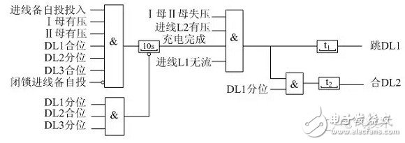
Figure 7 incoming line 2 alternate schematic
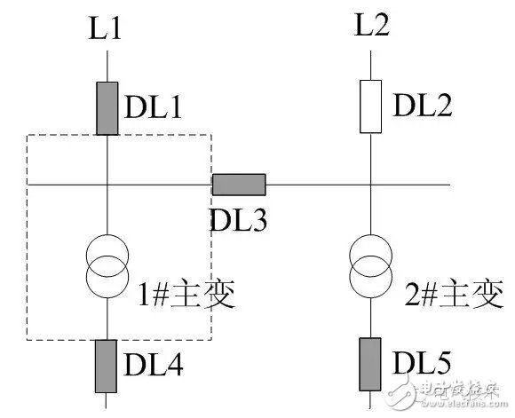
When a fault occurs in the dashed box as shown in Fig. 7, the #1 transformer protects the DL1, DL3, and DL4 and isolates the fault point. Since the DL3 is changed from the merging position to the grading position, the incoming line is not satisfied with the charging condition, the incoming line is prepared for the power supply, the DL1 and DL2 are the grading, and the entire station is de-energized.
If the #1 main transformer protection action DL1, DL4 trips successfully, DL3 trip fails, then the I mother, the II mother lose pressure, and the DL1 is the jump position, no flow, the incoming line L2 has pressure, and the incoming line is self-injected to meet the operating conditions. The DL1 will be cut by a delay, and DL2 will be combined. Because the fault still exists, the power will be led to the fault, which will impact the power grid and DL3 and DL2, which is not conducive to the safety of the power grid and equipment. Therefore, the incoming line is prepared by self-injection to act as one of the blocking conditions for the self-injection.
If the transformer protection action is successful, after the DL1, DL3 and DL4 are disconnected, the fault has been isolated. At this time, the DL2 is closed, and the line L2 can be supplied to the low-voltage side feeder through the switch DL2, #2 main transformer and DL5 to reduce the load loss. Improve power supply reliability. Therefore, it is not appropriate to use the transformer protection action as the blocking condition for the incoming line to be self-injected. Instead, it should be taken with the DL3 and the AND logic as the operating condition of the incoming line.
For the L1 line failure, the line protection cuts off the DL1, and the incoming line is ready to operate correctly. The logic diagram of the action of the incoming line can be improved as shown in FIG. 9 and FIG.
The improved incoming line preparation plan 9 and 10 are not only applicable to the substation with internal bridge connection, but also to the substation with single bus section connection, as shown in Figure 11. In the substation of the 110kV single-bus segmented wiring type, according to the status of the substation in the power grid, the protection direction of the high-voltage side protection of the main transformer is divided into two directions: the pointing bus and the pointing transformer.
If the protection direction of the high-voltage side is directed to the busbar, take the dotted frame in the figure as an example. When the I busbar fails, the #1 main transformer high-voltage side protection action, first remove the bus-tie DL3, and separate the two busbars from the fault, so that the fault-free busbar Keep running. If the protection component does not return, it indicates that the fault is in the I-segment bus and continues to jump off the main-side switches.
However, the fault still exists and the fault can only be removed by the un-oriented IV segment of the line switch DL1. At this point, the line switch DL1, the bus switch DL3, and the #1 main transformer high side switch DL6 are turned off, and the I mother is de-energized. Since the bus switch DL3 switch is turned off, the incoming line is self-injected and does not operate correctly. In fact, the DL2 switch of the incoming line L2 can completely operate the main transformer of the #2 main transformer and supply power to the low voltage side.
Figure 8 improves the backward line L2 standby logic
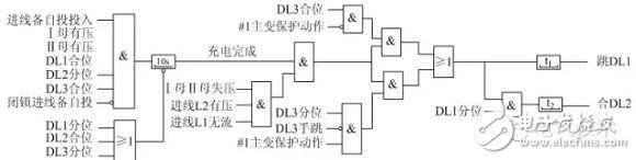
Figure 9 improves the incoming line L1 backup logic
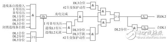
Figure 10 single bus segment wiring
4 Conclusion
In this paper, the following conclusions are drawn from the analysis of the voltage-current loop and the self-injection device design of the inner bridge wiring substation:
(1) Voltage loop. The bus voltage should be obtained by connecting the line voltage through the line side knife auxiliary contact, the switch and the auxiliary contacts of the two side knife gates in series;
(2) Current loop. The high-voltage side switch CT winding polarity for transformer differential protection should be opposite to the winding used for line protection.
(3) Investing in the line. The main trip trip should not be locked by the self-injection action, and the condition of the self-propelled action is added to the segment switch position, which makes the self-injection more accurate and improves reliability.
Cast Iron LV 3PH Asynchronous Motor
Cast Iron Lv 3Ph Asynchronous Motor,Three Phase Asynchronous Cast Iron Motors,Cast Iron Motors,Cast Iron Electric Motor
Yizheng Beide Material Co., Ltd. , https://www.beidevendor.com