The general battery charger uses a transformer to perform voltage transformation and charging, and has the advantages of large volume, easy heating of the transformer, and automatic prevention of charging. This charger can avoid the above problems due to the use of thyristors and integrated circuits. The circuit is as shown.
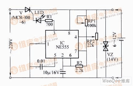
Battery charger control circuit
Circuit working principle: After connecting the battery to be charged, the IC is powered, and the pulse current is output from the third pin to trigger the unidirectional inter-tube work. The role of RP1 is to change the frequency of the pulse current, thereby changing the conduction angle of the thyristor and changing the charging current. The role of RP2 is to trigger IC pin 4 when the battery is full, so that IC pin 3 stops outputting pulse current and stops charging.
Component selection: RP1 and RP2 are trimming resistors, R1 and R2 are carbon film resistors, C1 is a ceramic capacitor, and C2 is an electrolytic capacitor. The IC is NE555, and the unidirectional thyristor can be selected from any intergranular tube (such as MRC-100-6) with a withstand voltage of 40 Ω or more and I ≥ 0.5A, and the VZ is a 14V voltage regulator tube. After the whole machine is installed, just adjust the required charging current of RP1, and then adjust the RP2 to control the battery to be fully charged and then stop charging.
This machine is suitable for charging batteries of 6~14V, but it can't be used to charge the battery (the resistance is too large). Since it is directly connected to the mains when charging, it is not possible to touch all the components on the machine by hand to avoid electric shock.
With the development of the times, the consumption level of people is gradually increasing. At the same time, people's entertainment methods are beginning to diversify, especially for modern young people. As a result, different kinds of electronic products are starting to be in people's lives, and the booming Electronic Cigarette industry reflects this.
Described including the upper shell, the upper shell at the top of the smoke outlet, as described in the bottom of the upper shell with airway, described with the smoke outlet in the airway and also to match the upper shell, the lower part of the shell described the airway in the direction of the lower shell extension, as described in the lower shell near one end of the upper shell is equipped with oil mouth, described the lower shell with batteries, described at the bottom of the bottom shell has come in The air port is provided with an oil storage bin in the lower shell, and the air passage passes through the oil storage bin and is provided with a heating atomization bin at one end away from the smoke outlet. The utility model has beneficial effects: it can meet the smoking habit of different users, avoid the premature end of the use experience caused by excessive consumption of smoke oil, and indirectly prolong the service time and life of the product.
Refillable E-Cig Oem,Refillable Vape Pod,Refillable Vape Pen Oem,Refillable Mod Oem
Shenzhen MASON VAP Technology Co., Ltd. , https://www.e-cigarettefactory.com