In conventional energy supply systems, batteries are widely used as the primary energy storage unit. With the development of science and technology and the need to protect the environment, supercapacitors have attracted much attention due to their advantages of large capacity, long life, fast discharge speed, wide operating temperature range, and can be used in series and parallel.
In the hybrid vehicle energy supply system, the battery energy storage system has such defects as low temperature characteristics, low life in a harsh environment, and difficulty in releasing large currents. Supercapacitors have the above advantages, not only can provide short-time high-power pulses, but also have excellent low-temperature properties, high lifetime and excellent internal resistance. Therefore, supercapacitors are widely used in hybrid vehicles.
Aiming at the problem that the supercapacitor has a large difference in cell voltage during the series use, which results in the energy storage efficiency reduction and accelerated aging of the ultracapacitor group, an ultracapacitor group management system using the battery pack monitoring chip LTC6803-4 is proposed. Realize the functions of single voltage, temperature monitoring and voltage equalization of the ultracapacitor bank. The experimental results show that the method has high detection accuracy, high speed and low power consumption, and can effectively monitor and manage the series super capacitor bank.
Compared with other electrochemical batteries, supercapacitors do not undergo chemical reactions during charging and discharging. They have the characteristics of fast charge and discharge speed, high power density, wide operating temperature range and long cycle life. They can be applied to microgrids and electric buses. And other fields. Since the supercapacitor's single-rated voltage is lower than 3 V, it is necessary to form an ultracapacitor bank in series in most applications. Under the influence of factors such as capacity deviation, leakage current and equivalent series resistance (ESR), the voltage difference of each supercapacitor cell will increase during the cycle. If the necessary equalization and management measures are not taken, the ultracapacitor group will be The energy storage efficiency is reduced, which affects the life of supercapacitors [2]. Therefore, it is necessary to develop a high-performance super capacitor bank management system to monitor the cell voltage and temperature of the ultracapacitor bank and perform voltage equalization control. Current management system designs often use high-precision A/D converters and multi-channel analog switches or optocoupler relays.
The LTC6803-4 is the second generation battery pack monitoring chip from Linear Technology (LTC). It has a 12-bit high-speed A/D converter that can measure the voltage and temperature of up to 12 series battery packs and measure 5 V. The following single cell voltage and temperature, the maximum total measurement error is less than 5 mV [5]. Up to 16 LTC6803-4 devices can be cascaded using an addressable SPI serial bus interface to monitor the voltage of each cell in more than 12 cells in series. The LTC6803-4 comes with a voltage equalization control function that can be used to set the equalization start voltage.
In this paper, an ultracapacitor management system is designed by using LTC6803-4. The system uses 32-bit microprocessor STM32F103 as the control core to realize the monitoring and display of the voltage and temperature of the 120 series super capacitor bank and the super capacitor bank. Perform voltage equalization control. Experimental results demonstrate the effectiveness of the method.
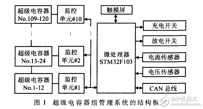
System hardware design system hardware overall frameworkThe ultracapacitor management system should have the functions of monitoring the voltage and temperature of the ultracapacitor group, voltage equalization, overvoltage and overcurrent protection, and data communication. The structure of the supercapacitor management system is shown in Figure 1.
Each 12-section supercapacitor constitutes a supercapacitor energy storage unit. A monitoring unit monitors the voltage and temperature of the cell in the supercapacitor energy storage unit, and voltage equalizes the ultracapacitor bank. 10 monitoring units (#1) ~#10) communicating with the microprocessor through the data bus connected in parallel; the microprocessor sequentially reads the single voltage and temperature data from each monitoring unit, and detects the total current and the total voltage of the ultracapacitor group through the current sensor and the voltage sensor. After data processing, it is displayed on the touch screen, and the microprocessor compares the sampled voltage, current, temperature and other information with the alarm value set by the system, and prevents the super capacitor bank by controlling the charging and closing of the charging switch and the discharging switch. Overcharge, overdischarge, overcurrent, short circuit and over temperature; can communicate with the host computer through the CAN bus for remote monitoring.

The microprocessor selects ST's 32-bit microprocessor STM32F103VET6 based on Cotex-M3 core. The microprocessor has the features of rich on-chip peripheral modules, low power consumption and convenient development. STM32F103VET6 has 80 independent input/output pins, 3 universal asynchronous serial communication interfaces (UART) and 1 CAN bus interface to meet the design requirements of this system.
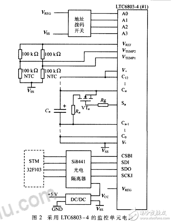
Monitoring unit circuitThe monitoring unit circuit uses the battery pack monitoring chip LTC6803-4. The main difference between the LTC6803-4 and the LTC6803-3 is the different communication interfaces. The LTC6803-4 uses an addressable SPI serial interface bus, while the LTC6803-3 is daisy-chained. The schematic diagram of the monitoring unit circuit is shown in Figure 2.
The LTC6803-4 communicates with the STM32 microprocessor via the optoisolator Si8441 isolated SPI bus. The Si8441 is powered by an isolated DC/DC module with 5 V output to ensure system safety and immunity.
C0~C12 of LTC6803-4 are single voltage detection pins, which are respectively connected to the two ends of 12 supercapacitor cells. C0 is connected to the lowest voltage end of the super capacitor unit, and C12 is connected to the highest voltage end.
The S1~S12 pins are voltage equalization control pins, which respectively control the equalization MOSFET VTn and the equalization resistance Rn in parallel with each super capacitor. When the LTC6803-4 detects that the cell voltage of a supercapacitor exceeds the set upper limit value, the corresponding MOSFET is turned on and discharged through the equalization resistor to achieve voltage equalization.
The V+ and V- pins are the positive and negative power supply pins of the LTC6803-4. When the parasitic power supply mode is used, the 12 series super capacitor units monitored by the chip can be directly charged. An independent power supply can also be used, but the power supply voltage is required to be not lower than the voltage of the supercapacitor energy storage unit under test. The LTC6803-4's normal operating current is less than 1 mA, and the power consumption in standby mode drops to 12 μA, which helps improve system efficiency.
VTEMP1 and VTEMP2 are two temperature-sensing A/D interfaces that use two 100 kΩ thermistors (NTCs) as temperature sensors and a 3.065 V voltage reference from the VREF pin.
A0~A3 are the 4-bit address input port of LTC6803-4. The address of LTC6803-4 can be set by 4-bit address dial switch. The address setting range is 0000~1001 (binary) to distinguish different monitoring units.

Maximum bandwidth in the HDMI 2.0 specification is 18Gbps. This bandwidth allows for support of 4K video resolutions at a higher refresh rates with more detailed color information than previous HDMI specifications. This configuration will also support advanced audio streams.
Refresh Rate
Higher refresh rates, up to 60Hz at a 4K resolution are supported within the HDMI 2.0 specification. This helps to reduce motion blur and lag and provides sufficient bandwidth for high dynamic range (HDR) and deep color content.
Chroma Subsampling
4:4:4 chroma subsampling per the HDMI 2.0 specification means that colors can be displayed uncompressed and in full resolution. Compliance with a 4:4:4 color spec is especially important when displaying content from computers and laptops.
Color Bit Depth
Color bit depth has increased to 12-bit deep color with 4,096 shades per channel outlined within the HDMI 2.0 specification. This allows for smoother gradients in displayed images than previous HDMI Specifications.
High Dynamic Range (HDR)
HDR expands the range of both contrast and color allowing images to achieve greater levels of detail in both bright and dark sections of the image. HDMI 2.0 was the first HDMI specification to support this feature.
Optimized Audio Performance
Support for advanced audio features such as DTS-HD, Dolby TrueHD & Dolby ATMOS allow for superior audio performance versus previous HDMI specifications.
Hdmi 2.0 Cable,Hdmi 2.0 B Cable,Best Hdmi 2.0 Cable,Micro Hdmi 2.0
UCOAX , https://www.ucoax.com