Application and realization of optical fiber communication in numerical control network
1 Overview:
CNC technology is a strategic basic technology for the modernization of the manufacturing industry. It is also an important strategic basic technology for improving the national comprehensive national strength and national defense modernization. With the development of digital drive technology and various manufacturing technologies, it has become an urgent need to improve the flexibility, scalability, portability, interoperability, interchangeability, and reusability of CNC systems. To this end, advanced industrial countries in the world have listed the development of open CNC system architecture as a key development plan. In order to adapt to this development trend and further improve the automation of factory production, CNC network systems will surely become the commanding heights of future CNC technology competition. . Solving the high-real-time and high-reliability transmission of data in this type of network is a core problem that constitutes a CNC network. This paper will focus on how to use fiber to achieve high-speed, high-reliability point-to-point transmission based on the characteristics of this network.
2 Features of network numerical control:
In the NC network system, the applied protocols are SERCOS (Serial Real-TIme CommunicaTIon System) and HSB (Highspeech Serial Bus). 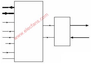
Figure 1 SERCOS network topology
The controller of the SERCOS interface can be connected to one or several ring structures as needed. The topology diagram in Figure 1 is just an example. It can also be seen from its topology structure that it uses a master-slave structure and a ring structure. The topology of HSB is simpler than SERCOS. It is mainly a master-slave structure. Due to the characteristics of the CNC system, it has relatively high requirements for data communication between the underlying devices, and must ensure high real-time and high reliability requirements. For example, the connection of CNC (Computer Numeric Controller) controller host unit and interpolation axis unit, drive unit, etc. This type of controller has a short control cycle of ms level, and requires higher communication reliability. Communication errors will cause more Serious consequences, such as scrapping of processed parts. In order to ensure that these requirements are met in the harsh environment of the factory, the communication medium of the formed CNC network must use optical fiber.
The typical communication cycle between such high-real-time and high-reliability bottom-layer devices is between 1 and 5 ms, and the typical effective communication data volume is between 500 and 2000 bits. The above characteristics determine the short cycle and short data frame of CNC controller communication. Therefore, when designing a point-to-point communication module on FPGA with VHDL at the physical layer, these basic requirements must be considered. Regardless of whether it is a SERCOS or HSB network, in order to be able to expand more nodes, the effective bit rate of point-to-point should be not less than 4M. Although the effective bit rate required by the network is greater than 4Mbps, due to the overhead of the protocol itself and to ensure high The amount of communication redundancy necessary for reliability, the actual communication bit rate in this type of network is much greater than the effective bit rate. Its communication efficiency is conservatively estimated to be only 15% to 30%.
3 Realization of optical fiber communication in CNC network
Regardless of whether it is a SERCOS or HSB structured CNC network system, when the bus control is obtained from the arbitrating slave station, the communication between the master station and the slave station is point-to-point communication. Therefore, according to the characteristics of the data transmitted in the CNC system, the realization of point-to-point high real-time and high reliable fiber optic communication is the basic link. This link is implemented at the physical layer.
The peripheral interface model for point-to-point communication at the physical layer is as follows: 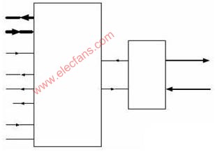
Figure 2 Peripheral interface model
This module is implemented in FPGA using VHDL language. Its function is to encode the data frame packed in the data link layer and transmit it to the bus through the optical fiber, and decode the received serial data from the bus to the data link layer. The main work of the physical layer is almost realized by this module.
The specific tasks of this module include: interface with the data link layer, interface with the optical fiber transceiver, data encoding and decoding, data serial-to-serial conversion, data oversampling or data clock recovery, data word alignment and other functions.
1): Interface with the link layer:
Outport [15..0]: Sixteen bits of data to be sent to the bus, the lower eight bits are the addresses of the upper eight bits of data.
inport [15..0]: Sixteen bits of data received from the bus, the lower eight bits are the addresses of the upper eight bits of data.
senddata: send a data signal, when it is given a transition, the data in the outport will be CRC, 4b / 5b encoded, and then serially sent from data_out.
Ack_y: When receiving a handshake signal sent by the other party to indicate that the other party has correctly received the data, it will jump.
Ack_n: When receiving a handshake signal sent by the other party, indicating that the other party did not receive the data correctly, it will make a jump.
Receive_ok: After receiving the data sent by the other party and the crc check is correct, it will have a jump, and at the same time output the data from the inport port, and send a frame for receiving the correct handshake signal to the other party. When the received data does not pass the crc check, receive_ok does not change, the data is not output, and only a handshake signal frame for receiving errors is sent to the other party.
2): Interface with optical fiber:
data_in: Serial data sent.
data_out: Received serial data.
3): Data encoding and decoding:
When sending data, first use 4b / 5b encoding, then CRC encoding; when receiving data, the other way around, first use CRC decoding, then use 4b / 5b decoding. The cyclic code generator polynomial used in this module is the European standard CRC-16.
4): Data parallel-to-serial conversion:
The 16-bit data in the outport is encoded and serially output, and the serial data received from the optical fiber bus is decoded and output in parallel in the inport.
5): Data oversampling or data clock recovery:
In the asynchronous communication mode, it is necessary to use the sampling method to judge the data transmitted on the medium 0 and 1 to generate the data at the receiving end. Due to the lack of phase information at the sending end in the asynchronous mode, it is difficult to ensure that the sampling point is located in the middle of the data, that is, communication In the middle of the “eye diagramâ€, the data there has sufficient retention time and is the best decision point. Therefore, the oversampling method is used at the receiving end. In each bit data period, the data is sampled 5 times, and the data occurs When the change of 0ï¼> 1 starts sampling, the sampling result in the middle is taken as the result of this sampling. The format of the data frame sent is as follows: 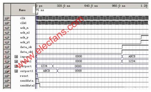
The types of frames sent are: data frames, handshake frames (receive the correct handshake frame and receive the wrong handshake frame), so in this module must solve their mutual exclusion and priority issues. In this module, it is implemented by the mechanism of the state machine: giving data frames, receiving correct handshake frames, and receiving wrong handshake frames, respectively, a sign bit: sign_data, sign_ack_y, sign_ack_n. When there are data frames to be sent, sign_data is set to 1. When the data frame is sent, sign_data is reset to 0, and the handshake frame is also the same. The status of the module is: idle, SendingAck_y, SendingAck_n, SendingData, and their state jump relationship is as follows: 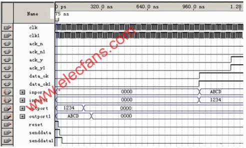
Figure 3 State machine jump diagram
It can also be seen from the jump relationship diagram that when there are both handshake frames and data frames to be sent, the handshake frame is sent first, because the handshake frame is much shorter than the data frame, so sending it first can improve Overall transmission efficiency. The operation of the data link layer to the module is: send the data frame to be sent to the ouport port, and then sendend a transition edge. This signal is the start signal. If the ack_y handshake signal is received, the next frame of data is sent. If the ack_n handshake signal is received, indicating that the transmission failed, it is retransmitted. If the handshake signal is not received within a reasonable time, it is defined as timeout and retransmission If the retransmission fails three times or fails, the system is notified by interruption and the communication fails. This can ensure the accuracy and reliability of data transmission in the CNC system. There will be no serious consequences caused by the failure of a frame of data transmission, such as the scrapping of the workpiece. 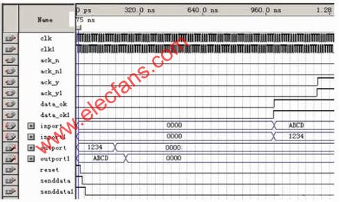
4 Simulation
The sampling clock used in this simulation is 100M (the actual sampling clock can be higher after synthesized by quartusII), as can be seen from the results: from the senddata transition, the data of the outport is latched, and the data transmission starts to be received and The period of the handshake signal is 1.15us. In these 16-bit data, the lower eight bits are the address and the upper eight bits are the valid data. Therefore, the effective bit rate is 6.95M, and the effective speed can fully meet the requirements of the CNC network. Although this is a simulation result, the effect when running in an actual numerical control system is the same as it. The debugging of the optical fiber communication module in the actual system has ended.
5 Conclusion
Today, as factory automation is getting higher and higher, the numerical control network system composed of optical fibers will greatly improve the core competitiveness of Chinese enterprises. Provide technical quality assurance for Chinese enterprises to fully participate in international competition.
Digital Load Cell is our new arrival load cells , digital output RS232 or RS485 , It made of aluminum alloy material, have 5kg, 10kg, 30kg , 40kg capacity and we recommend the max platform of it is 250×350mm.C4 high accuracy load cell, used for electronic counting scales, smart shelves, etc which needs high quality weighing condition.
Digital Load Cell,Electronic Load Cell,Load Cell With Digital Readout,Digital Load Cell Weight Sensor,load cell 5kg
GALOCE (XI'AN) M&C TECHNOLOGY CO., LTD. , https://www.galoce-meas.com