Design scheme of MMS alarm system based on GPRS and single chip microcomputer
Abstract: Design a multimedia message alarm system based on GPRS and 51 single chip microcomputer. Using single-chip technology, GPRS wireless communication module with MMS protocol, image capture and image compression coding function module, realize schematic design to circuit board design and development. The single-chip computer controls the serial port camera image acquisition and compression processing according to seNSor, and the collected image is sent to the user's mobile phone through the format of the multimedia message. At the same time, the system status can be viewed at any time through the short message command, or the camera collects images and monitors the scene.
The traditional electronic anti-theft alarm system in China often detects theft and other alarm information through the electronic device at the user end, and then automatically transmits the signal to the alarm center via the telephone line through the communication line to complete the alarm process. Such alarm centers often have many limitations. For example, the location and personnel of the alarm center need to be fixed, the alarm communication speed is slow, the reverse query and control operations are difficult and professional, the telephone line disconnection problem is difficult to solve, and the communication cost, especially the remote communication cost is high, which is not conducive to the establishment of a remote network. The communication bandwidth is too small, the amount of information to be loaded is small, and the technical means of audio and video signals are difficult to apply, and it is difficult to apply to the home security market and the like.
Since the official launch of China Mobile's mobile phone business in September 2002, with the establishment and continuous optimization of MMS network engineering, MMS has gradually entered a stage of rapid development and stable application. Therefore, people are paying more and more attention to relying on China Mobile's network and MMS based on the development of modern electronic anti-theft alarm system, so that they can monitor their operation anytime and anywhere, the network coverage is large, the query control is easy, and the cost is low. The advantages of fast alarm communication, easy application of audio and video, etc., make it widely used in homes, offices, factories, shops and other places.
1 system hardware design
1.1 System bus design
The MMS alarm system uses the ordinary AT89C52 MCU and the wireless module GPRS with MMS function. The front-end device can collect pictures according to the control camera and send them to the user's mobile phone. At the same time, the user can view the system status at any time through the SMS command, or control the front-end camera to collect images. , monitoring the situation on the spot. The products designed by this scheme are simple to operate. In order to reduce the cost, on the basis of the minimum hardware design, the functions of the system are implemented by software programs as much as possible to reduce costs and meet market demands.
The designed hardware circuit is mainly composed of three parts: image capture and image compression coding part is realized by serial port camera; main controller processing image data and task control are realized by AT89C52 single-chip microcomputer; wireless part of GPRS module with MMS protocol. In the design of the use of circuit diagrams, in the design process, the hardware structure block diagram is first designed, as shown in Figure 1:
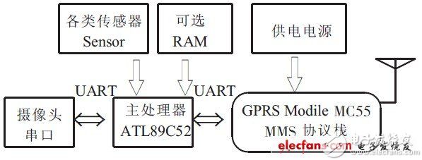
Figure 1 system hardware block diagram
Using MCU AT89C52 as the core to form a multimedia message alarm system, AT89C52 has a fast 8051 core, 8kBFlashE2PROM, 256BIDATARAM, which meets the hardware requirements; MMS alarm function, MC55 chip with GPRSModule, with MMS function of MMS protocol stack; real-time capture and image with serial port camera Compress storage.
1.2 MCU interface design
In the AT89C52 MCU interface, as long as a set of serial ports, GM8123 can expand a full-duplex standard serial port into three standard serial ports, and can control the serial port expansion mode through external pins. The working baud rate of the chip serial port and sub-serial port can be adjusted by software without modifying the external circuit and crystal frequency. It has less external control, flexible application and simple programming. It is suitable for most systems with serial port expansion requirements. Therefore, the GM8123 is used to expand the three serial ports for the AT89C52, which can communicate with the serial port camera and the GPRS module. as shown in picture 2.
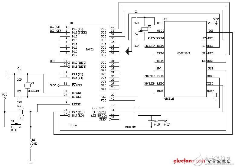
Figure 2 MCU interface circuit design
1.3 GPRS data transmission module hardware design
Since the live picture needs to be sent in the form of MMS, the wireless module with MMS function is selected. The GPRS module selected here is the MC55 [5] of Siemens. The data communication between the GPRS module and the MCU is mainly through the ports TXD0 and TXD1. The data transfer between RXD0 and RXD1 is completed. The TXD0 port on the GPRS module is used to receive data transmitted from the MCU, and the extended TXD2 port on the MCU is used to transmit data to the GPRS module. The RXD0 port on the GPRS module is used to send data to the MCU. The extended RXD2 port of the MCU is used to receive data transmitted from the GPRS module.
The circuit schematic of the hardware part of the GPRS data transmission module is shown in Figure 3.
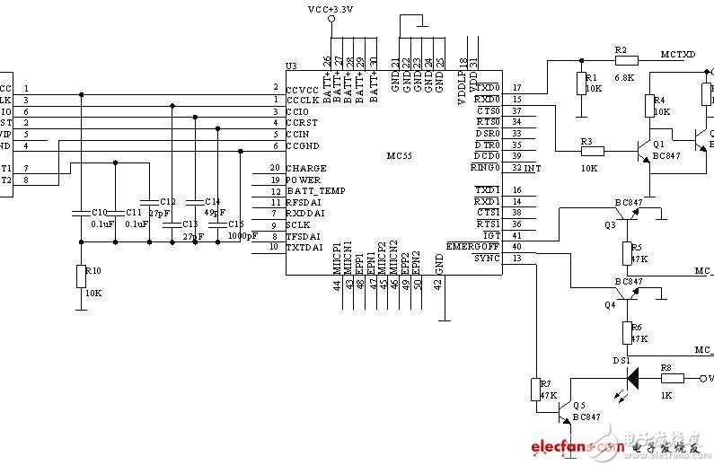
Figure 3 GPRS data transmission module circuit design
1.4 serial camera
The ZSV-01P serial camera is a camera with video capture and image compression. It has a 1.3 megapixel CMOS camera with a maximum resolution of 1 280×960. It is a camera with capture control, video capture, image data acquisition, and image capture. A complete industrial image acquisition device with JPEG compression, serial communication and other functions, the maximum serial communication speed can reach 115.2kbs [6]. The camera with serial port used in this design, the host controls the camera through the serial port under the agreed protocol. The host and the camera are a master-slave relationship. The camera's operation commands are issued by the host. The host can control the camera's output format and resolution, and the camera sends a response message to the host. Specific parameters:
(1) Interface: RS-232 standard interface between the host and the camera, the baud rate is 57 600, 8 data bits, no parity, 1 stop bit.
(2) Image format: The image format output by the camera is JPEG.
(3) The image resolution may be: 640 × 480, 320 × 240, 160 × 120, 352 × 288, 176 × 144. The higher the image resolution, the larger the amount of image data. Figure 4 shows a complete picture acquisition process for packet transmission.
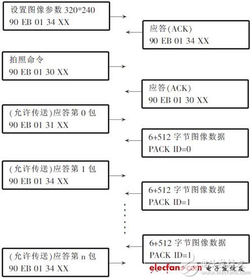
Figure 4 Serial port camera acquisition process
2 software design
2.1 Module software design
The software is built using the standard C language and compiled by the Keil C51 compiler. The system software design consists of two parts: one is the write of the control word of each function chip and the serial port expansion program of the single-chip microcomputer; the second is the GPRS data receiving and sending program design.
2.1.1 MCU and GPRS wireless module
This program is mainly to complete the data transmission between the GPRS module and the single-chip microcomputer. The single-chip microcomputer has 51 series. The set serial port serial port working mode is mode 1, 8-bit UART, the data transmission rate is variable; the timer 1 The working mode is mode 2, the data transmission rate is set to 9 600 b/s, and the crystal oscillator is 11.059 2 MHz. The main transmission is the AT command, including the dialed number, the IP address of the DNS service, and the password of the GPRS service provider. APN accessing the GPRS service. Of course, a TCP communication is also required. The client content of the service includes the information transmitted by the IP, the address, and the TCP port number of the remote host.
The main program of the program is to send and receive AT commands. When the data is sent and received, the data transmission subroutine and the data receiving subroutine are respectively called. Here, there are three subroutines: data transmission subroutine and data receiver. Program and delay subroutine.
2.1.2 The control process of the MCU camera.
When the host acquires the camera image, it operates: (1) open the serial port; (2) start capturing images, set the image resolution; (3) acquire image data; (4) end the acquisition of images; (5) close the serial port. Step (3) Acquiring an image can be performed cyclically. If you reset the image resolution, you should perform step (2) again.
2.1.3 Single-chip serial port extension program design
The status and meaning of each port associated with it is:
(1) sbit MS=P3^6; //GM8123 working mode control
(2) sbit RESET=P3^7; //GM8123 reset pin control
(3) unsigned char SendBuff[5]={ 0x67,0xbc,0xc9};// requires three sub-serial ports
Defined in the main program:
TMOD = 0x20; // specify timer 1 to work in mode 2
IE = 0x90; // open serial port interrupt
SCON=0xc0; // Serial port works in mode 3
TH1 = 0xf8; // Load the initial value of Timer 1, set the host operating baud rate to 7 200bs
P1=0x00; // Set GM8123 command word address
SBUF=Contr_data; // Set the baud rate of the GM8123 sub-serial port to 19 200bs, and the baud rate of the parent serial port is 11 5200bs.
Therefore, the entire control process is: define and initialize the control words and ports of each component, and then the microcontroller sends commands through the serial port to check and control the operation of each Sensor and serial camera and MCC55.
2.2 Program flow
After the system is powered on, first initialize the MCU, set the baud rate and timer of the serial port; then initialize the GM8123 and various Sensor sensors; then execute MC55 to power on, then initialize MC55.
The system program flow is shown in Figure 5.
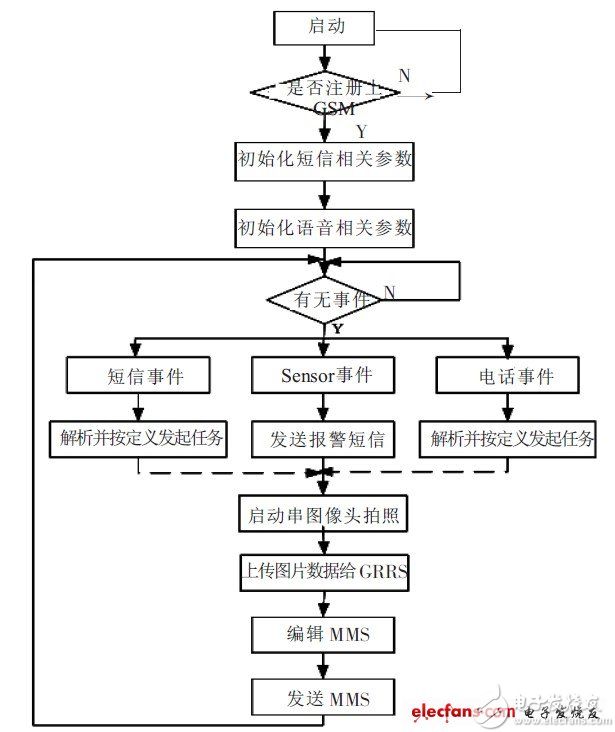
Figure 5 system program flow chart
3 Conclusion
This design selects the serial camera of Zhongshen Microelectronics Co., Ltd. to realize image capture and image compression coding, which simplifies the complexity of the circuit. The wireless part of the GPRS module with MMS protocol selects MC55 of SIEMENS company. The module has stable, reliable and operation performance. Convenience. It is verified by experiments that the alarm system works well, and the user can remotely control the mobile phone anytime and anywhere, and take photos of the scene and send it to the designated mobile phone or e-mail. Can be connected to a variety of wireless sensor alarms, such as smoke, wireless door magnets, infrared body sensors, gas sensors, etc., to achieve a variety of trigger mode alarms, and with image motion detection, can automatically trigger alarms on moving objects, Has a certain practical value.
Barrier Strip Connector ,Barrier Type Terminal Block ,Dual Row Terminal Block ,Barrier Terminal
Cixi Xinke Electronic Technology Co., Ltd. , https://www.cxxinke.com